ANEW Can Help With Road Safety
Smart tires with ANEW device features can help drivers make risk-free decisions and can help build autonomous vehicle control systems with future tires.
Join the DZone community and get the full member experience.
Join For FreePrelude
Self-driving cars can change everything in terms of road safety and mobility. Self-driving vehicles are capable of sensing their immediate environment and can move safely with little or no human input. With self-driving cars, real-time alerting systems act as a communication between vehicle and driver. Real-time signaling and alerting have many tangible and intangible benefits.
XYZ’s “Autopilot and Full Self-driving capability” has been getting better every year since its introduction. XYZ's patent to “Automate Turn Signals” is an advanced step in enhancing road safety, not only for self-driving cars but also for drivers who ignore or forget to use turn signals. There is always a question, how independent should a vehicle be in making smart decisions? Self-driving cars should be just as intelligent as the driver in making the right decisions.
Autopilot consists of eight external cameras, radar, 12 ultrasonic sensors, and a powerful onboard computer to guide for a safe journey. What is the role of tires? Smart tires, in real-time signaling and alerting, are the only things to touch the ground, and their movement is key in changing lines and turns.
Automatic turn signals are dependent on a steering angle data source with respect to ultrasonic data sensors. A small percentage of car manufacturers can provide these additional safety measures for auto signaling and alerting, as it would be very complex and expensive for every manufacturer to come forward with these kinds of developments.
Smart tires can play a key role in this kind of development to provide additional safety and be cost-effective. Smart tires provide not only automatic signaling features but also help to detect misconstructed roads and avoid fatal toppling.
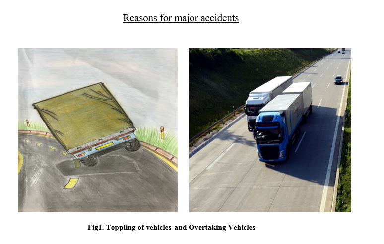
In this article, we will introduce a smart tire and explain how this will help tire manufacturing companies design a set of sustainable solutions to ward off various road mishaps, output an intercept to identify an overtaking vehicle, and to signal a quick estimate of all forms of rough terrains (wrongly designed angle of banks, misconstructed roads) to keep especially heavy vehicles from fatal toppling. In this pursuit, we will affix a tire internally with well-calibrated and cost-effective, non-cumbersome mechanical semi-micro tools such as Magnetometer, which is a compass, and Gyroscope, which both work together to help input an edge computing instrument to output a quick intercept to the driver.
Smart tires in the tire industry give huge insights into driving analytics and much more real-time analysis. TPMS — Tire Pressure Monitoring systems are definitely an additional safety for vehicles and drivers. However, is this the only information that can be made use of from tire data? There is abundant information available from tires that can be used to generate more safety for both vehicle and driver. Safety through smart tires is a cost-effective solution that can be helpful to the majority of drivers instead of focusing only on self-driving cars, which will cover only a small percentage of cars in use.
Smart tires' real-time alerting and signaling can be more effective than depending on vehicle dynamics, as tires are the only thing in contact with the ground; tire parameters can play a key role in drive analytics and help in avoiding major road mishaps. Automatic turn signals, which are dependent on steering angle data source, might be inaccurate when a vehicle takes a turn at a lean angle. This kind of alerting can be more accurate if we source data from tires instead of steering angles.
A well-calibrated digital compass from Accelerometer, Gyroscope, and Magnetometer using sensor fusion methodologies can give accurate data. The three major challenges that have to be monitored and controlled in major accidents are overtaking vehicles, angle of banking, and fatal toppling due to misconstructed roads. MEMS are Microelectromechanical systems or micro machines which were made up of components of size between 0.001 to 0.1 mm. They are made up of a central unit that processes data and multiple components that interact with microsensors. Using a MEMS accelerometer, gyroscope, and magnetometer, we can create an application of a digital compass that sources data from these microsensors. In this article, we will see how we can model a device that can be affixed internally in a tire with good calibration, thereby resulting in a digital compass based on tire movement. This device, the ANEW-Angular Navigation Early Warning device, can help to control below three major road mishaps.
ANEW Architecture
Firstly, we can look at below designed architecture of the ANEW device and process flow. Data that is recorded through microsensors is processed with an algorithmic model to reduce noise from sensors or stochastic errors due to nonlinearity; this will result in an accurate digital compass that can provide real-time alerting.

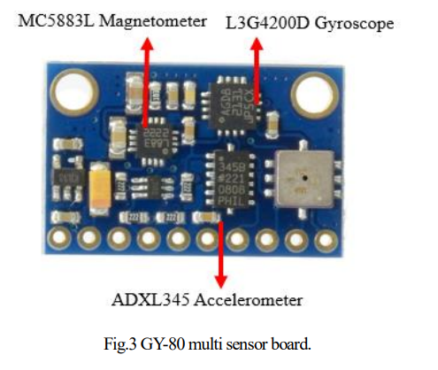
The two main segments in the entire architecture are the Sensors & Optimal estimate algorithm that have been used. These two play key roles in this product development. We will first see how to calibrate these multiple microsensors. We are using a GY-80 multi-sensor board, which comprises of accelerometer, gyroscope, and magnetometer, as shown below:
MEMS Accelerometer
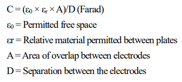
Motion sensors like MEMS accelerometers are characterized by small size, lightweight, high sensitivity, and low cost. Accelerometer measures acceleration by measuring a change in capacitance. The primary component of the GY-80 multi-sensor board is the ADXL345 digital accelerometer. Accelerometers Operations are based on Newton’s (1) Second law of motion, which says that the acceleration (m/s2 ) of a body is directly proportional to and in the same direction as the net force (Newton) acting on the body and inversely proportional to its mass (gram).
This sensing technique is known for its high accuracy, stability, low power dissipation, and simple structure to build. Bandwidth for a capacitive accelerometer is only a few hundred Hertz because of their physical geometry (spring), and the air trapped inside the IC acts as a damper.
MEMS Gyroscope
Microelectromechanical systems gyroscope that measures the angular rate by using Coriolis Effect comes with low cost, small device size, low power consumption, and high reliability leading to increasing applications in various inertial fields. Coriolis effect(2) or Coriolis force is nothing, but when an object is moving in a direction with a certain velocity and when any external angular rate is applied, the force will occur, which causes the perpendicular displacement of mass.
MEMS gyroscope measurements are affected by errors, as they are prone to drift. In our next sections, we will see how this drift in values is handled through sensor fusion techniques. For the ANEW device, as we are using a GY-80 multi-sensor board, it comes with an L3G4200D gyroscope by default.
In general, values between the accelerometer and gyroscope and combined in order to remove extra noise or drift in values from the gyroscope; this works as these sensors come with complementary filters. However, when we use these sensors on the tires of a traveling automobile, where rotations are very high, the noise will be more. These default complementary filters will not be helpful in ANEW device, which is planned for tires. These gyroscope readings are critical for us to predict the fatal toppling of vehicles. By default, the values between the accelerometer and gyroscope are integrated into our mathematical model.
MEMS Magnetometer
The third sensor in our GY-80 multi-sensor board is the MC5883L Magnetometer, a MEMS magnetometer that works on the Hall effect(3). Hall Effect sensors are used to measure the magnitude of a magnetic field. Its output voltage is directly proportional to the magnetic field strength through it. In general, a basic magnetometer that works on Hall Effect is quite sufficient to develop a digital compass by using a processing development environment. This can help in automating turn signals with proper calibration.
As we are addressing here the toppling of vehicles which is caused due to angle of banking or misconstructed roads, we are using a GY-80 multi-sensor board consisting of an accelerometer and gyroscope.
We have seen the first part of ANEW architecture, which is the ANEW device and the type of sensors we are going to use to develop a digital compass. Instead of directly moving to develop a digital compass, first, we have to address how we are going to manage additional drift that will come from the gyroscope. To handle these stochastic errors, we will be using an “Unscented Kalman Filter” in our algorithmic model; then, final values are displayed over a digital compass, which will result in automatic alerting.
Kalman Filter
Kalman filter is an optimal estimation algorithm; it is used to extract information about what you cannot measure from what you can. It is used to determine the best values from noisy measurements. Why do we say noisy measurements, and what is drift? For example, a cup of hot coffee measures 450C, the thermometer reads 44.60C for the first time and then reads 45.50C the second time. We will not get the same number each time. State estimation algorithms provide a way to combine all noisy values and give a better estimate.
Our data from the GY-80 multi-sensor board is all sensor data that we receive, specifically gyroscope data, which is prone to much drift, so we need a better estimate algorithm to handle these noisy measurements. The technique here is to fuse data from multiple sensors to produce the correct estimate. In our case, it's data fusion between the accelerometer and gyroscope.
Kalman filters are basically defined for linear systems. The Linear system process model defines the evolution of state from time k-1 to time k as(4):
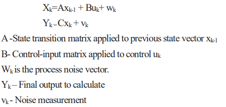
The above process model is for linear systems. Below is the probability density function to show the working principle of the Kalman filter for linear systems to find the position of a moving car(5).
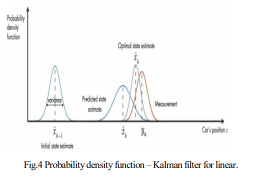
However, in our ANEW device model, we are going to fuse the accelerometer and gyroscope in order to handle drift. Due to the non-linear relationship between angular velocity and orientation, it is unclear whether the magnitude of the angular velocity and its distribution across the three gyroscope axes may alter the effect of the considered noise types(6).
Now, taking into consideration of non-linear system, our set of linear system equations will change as below: State transition function and measurement function becomes non-linear.

In this case of nonlinear transformations, the Kalman filter is not useful, whereas the Extended Kalman Filter comes in handy, which linearizes nonlinear functions. When a system is nonlinear and if it can be well approximated by linearization, then the Extended Kalman filter is a good option. However, it has a few drawbacks; the major drawback to highlight here is that Extended Kalman Filter is not a good option if the system is highly nonlinear. For proper system dynamics with the ANEW device, both the Kalman filter and Extended Kalman Filter will not help much as linearization becomes invalid as our system is highly nonlinear and cannot be approximated.
The solution to approximate our highly nonlinear system is Unscented Kalman Filter.
Unscented Kalman Filter’s (UKF) approximates the probability distribution. In this model, UKF selects a minimal set of sample points or sigma points so that their mean and covariance are exact.
Each sigma point is propagated through a nonlinear system model; the mean and covariance of nonlinearly transformed points are calculated to compute the Gaussian distribution, which is a probability distribution. It is further used to calculate new state estimates. Below is the standard process model to implement the Unscented Kalman filter(7). Describe the difference equation and observation model with additive noise:

Let's see this implementation in the ANEW device:
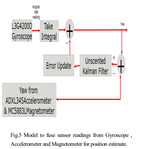
We are trying to fuse three sensor data: accelerometer, magnetometer, and gyroscope, which has high noise. Below is the process flow structure of the Kalman filter-based position estimate algorithm.
Here from the above equation, Zk is the output observed model with added noise vk. The first step is to apply an unscented transformation scheme to the augmented state:

In the next step, we have to set the selection of Sigma points. Then in the model forecast step, each sigma point is propagated through the nonlinear process model, which is(7):

Next, in the data assimilation step, we combine information obtained from the forecast step with the newly observed measure zk. As per the standard model, we need to obtain the square root matrix of covariance each time to compute a new set of sigma points, which gives us a measurement update summary.
Digital Compass
As we have seen two main segments in the ANEW device process flow, the GY-80 multi-sensor board and the Unscented Kalman filter algorithm and their working principles, let us see how we can set up a digital compass. A digital compass or an electronic compass is basically a combination of multiple MEMS sensors, which provide orientation and measurements in multiple applications.
As highlighted earlier, to set up a digital compass, only a magnetometer is sufficient, but to avoid noise measurements, as shown in Fig.5 Model, fuse sensor readings from Gyroscope, Accelerometer, and Magnetometer for a position estimate. We will fuse all the sensor values to have the final output in the digital compass. Connect all sensors to Arduino board which works on I2C (Inter-Integrated Circuit) protocol. In the process development environment, where Arduino wire libraries are used to set up and start serial communication.
Unique device addresses and their internal register address can be scraped from data sheets. ADXL345 datasheet (8). The loop section is similar for all sensors, where we calculate row data for every axis. The sensitivity of sensors is defined as per requirement here (+250 dps to +2000 dps). Angular from the gyroscope is calculated and given as an input parameter into our algorithmic model.
Observer state in the model where we integrate measurements from the accelerometer and magnetometer are passed for the error update step. The final estimated values are then brought to a serial monitor that can be displayed on the digital compass. Based on these values, digital compass values are then set for automatic signaling and alerting. Finally, this data is again captured for drive analytics.
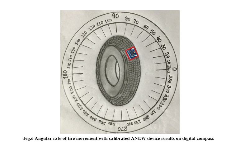
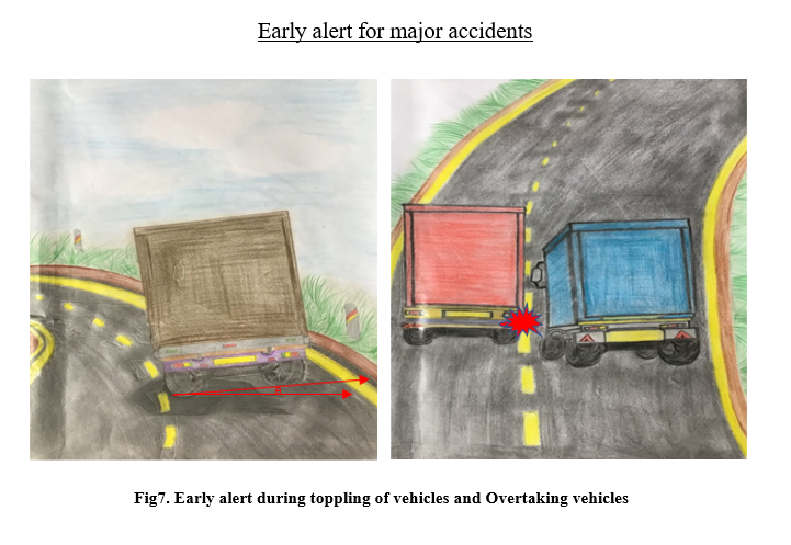
The reasons highlighted for major road mishaps are available in Section 1. The movement of the tire is well-tracked to alert automatically during overtaking vehicles (auto turn alert based on tire movement). Fatal toppling due to the angle of banking or misconstructed roads are alerted by monitoring the angular rate of tire movement.
Conclusion
Self-driving cars are getting better every year. Auto turn signals have opened doors that technology is not only for self-driving cars. There is a larger scope for introducing new technologies. When we look at smart tires, as tires are the first thing that comes in contact with the road, there is plenty of untouched data from tires till now, which can be used for greater insights that can help increase road safety and mobility.
Major road mishaps that occur during overtaking vehicles due to the angle of banking and misconstructed roads are well handled and predictable through the ANEW device and can be avoided to a maximum extent. Smart tires with ANEW device features can help to make risk-free decisions on misconstructed roads, avoiding fatal toppling, and can help build autonomous vehicle control systems with future tires. The core idea of this concept and help build tire-manufacturing companies to design a set of sustainable solutions to ward off various road mishaps.
Opinions expressed by DZone contributors are their own.

Comments