UE Application Initiation and Offloading on MEC Deployments in a Standalone 5G Network
Learn more about MEC hosts deployed in a 5G network.
Join the DZone community and get the full member experience.
Join For Free5G is a disruptive technology mandatorily needed to meet the capacity and performance requirements of future networks. Massive bandwidth needs and extremely low latency requirements, needed by burgeoning applications (like AI, IoT, AR/VR), require 5G to be facilitated by other emerging technologies like SDN/NFV and multi-access edge computing (MEC). By bringing the computing closer to the user, MEC promises to meet the desired latency and bandwidth constraints. Standardization bodies, like 3GPP (for 5G) and ETSI (for MEC), have been working towards streamlining the procedures for interworking of 5G core and MEC systems. The 5G and MEC specifications give an insight into the future integration strategy expected – making MEC work as a 5G application function to interact with the 3GPP 5G system for traffic steering and reception of mobility events. But a complete flow of information between MEC function entities and the 5G core network functions on application initiation and UE mobility seems to be missing at this point of time. This paper intends to dig into some of these interworking issues and explains the interactions between the participating entities during the complete application lifecycle.
Keywords — MEC (Multi-access edge computing), 5G (5th generation), UE application offloading, 5G application functions
Introduction
Multi-access edge computing is instrumental in accomplishing the desired KPIs of ultra-interactive, rich user applications in 5G deployments. To achieve this kind of performance, the UE applications are split into modules, of which the CPU intensive and latency-sensitive ones are hosted in the network edge closest to the consumers. Since this is part of the network-structure, it requires inter-working between the UE application front-end, the network functions deployed on the MEC edge host, and the 5G core network functions when deploying these MEC hosts into 5G networks. Additionally, the UEs are expected to be mobile. The MEC host handling the UE application may become non-optimal due to change in the UE location. Thus, to maintain the application’s performance requirements, application offloading from one MEC host to another might be needed. Detecting when the application offloading is required and the changes needed in steering UE traffic towards the new MEC host would, again, require support from the 5G core network functions. This paper intends to show the inter-working between MEC functional entities and 5G core network functions for running the UE applications on MEC hosts deployed in a 5G network.
The remainder of this paper is organized as follows. Section II mentions some practical use cases where UE application offloading will play a crucial role. Section III introduces the MEC-5G integration and the kind of challenges faced in such deployments. Section IV to Section VIII detail the complete procedural flows between the MEC systems and the 5G core whenever a UE application processing is supposed to be offloaded to the edge.
Before moving forward, we recommend a quick read of Appendix A.1 (Introducing 5G core network functions entities) and Appendix A.2 (Introducing the MEC functional entities) to get familiarized with the terms used later in this paper. Table 1 lists the abbreviations used across this paper.
II. Use Cases
When the underlying network supports UE mobility, the UE might move to a network entity connected to a different ME host than the current serving ME host. Enabling the new MEC host to serve the UE requires maintaining connectivity between UE and mobile edge application instance and application instance relocation or UE state/context relocation. Few cases where UE mobility might trigger this kind of application offloading to a new MEC host are UE bearer path changes in the underlying network, which leads to the UE moving out of coverage area of source ME host to the coverage area of another ME host (target).
Mission-critical low latency applications require latency in a few milliseconds. To support such low latency, the ME application needs to be relocated close to the user if the user moves from one cell to another.
3GPP |
3rd Generation Partnership Project |
NAS |
Non-access stratum |
5GC |
5th Generation Core |
NEF |
Network exposure function |
AF |
Application Function |
NF |
Network Function |
AMF |
Access and Mobility management Function |
NRF |
Network repository function |
APPD |
APPlication Descriptor |
OSS |
Operation Support Systems |
CN |
Core Network |
PCC |
Policy and Charging Control |
CUPS |
Control and User Plane Separation |
PCF |
Policy Control Function |
DN |
Data Network |
PDU |
Protocol Data Unit |
DNAI |
Data Network Access Identifier |
PGW |
Packet Data Gateway |
DNN |
Data Network Name |
PLMN |
Public land mobile network |
EPC |
Evolved Packet Core |
RAN |
Radio Access Network |
FE |
Functional entities |
RAT |
Radio Access Technology |
FQDN |
Fully Qualified Domain Name |
SGW |
Serving Gateway |
GPSI |
Generic Public Subscription Identifier |
SMF |
Session Management Function |
GUAMI |
Globally unique AMF ID |
S-NSSAI |
Subscribed Network Slice Selection Assistance Information |
GUTI |
Globally unique temporary identifier |
TA |
Tracking Area |
KPI |
Key performance indicators |
TAI |
Tracking Area Identity |
LADN |
Local Area Data Network |
UDM |
Unified Data Management |
LCM |
Life Cycle Management |
UDR |
Unified Data Repository |
MEC |
Multi-access edge computing |
UE |
User Equipment |
MEO |
Mobile Edge Orchestrator |
UL |
Uplink |
MEP |
Mobile Edge Platform |
UPF |
User Plane Function |
MME |
Mobility Management Entity |
URI |
Uniform Resource Identifier |
Table 1: List of Abbreviations
III. Defining the Problem Statement
The advancements made in 4G have proved to be a strong basis for the 5G networks. 4G EPC leveraged the CUPS architecture — control plane and user plane separation. With virtualization, independent scalability of the network nodes, SGW and PGW, became easy. 5G is a further improvement to this approach. SGW-C and PGW-C are completely separated from SGW-U and PGW-U, moving all the user plane functionality (for instance – packet routing/forwarding, policy rule enforcement, QoS handling, traffic usage reporting) to a new 5G function called “User plane function” or UPF. MME, SGW-C, and PGW-C functionality of 4G are moved to AMF and SMF in 5G. To achieve the desired modularity expected in NFV-based functions, access management and mobility management are moved to AMF, and the user session management is moved to SMF.
A standalone 5G network is based on a services-based architecture (clause 4.2 of [1]) — each network function (AMF, SMF, NEF, and others) in 5G is an independent service that can provide certain services to other components. These services can be independently accessed and updated. This capability is crucial for 5G-MEC deployment interworking also since it becomes feasible for the MEC functional entities to use the service-based interfaces of the 5G core network functions and retrieve/update relevant information. For instance, these interfaces can be used by MEC functional entities to retrieve the UE locations or pass the traffic rules to the 5G core network. This makes it possible to achieve, for example, mobile application offloading from one LADN to the other, as discussed in our original use cases (II. Use Cases).
Separating user plane completely to UPF helps in individual placement and scaling of user plane and control plane in 5G. The UPF can now be placed close to the edge of the network and can be integrated with MEC hosts in the access network. The MEC hosts lie in the path between UPF and the data network, as shown in Fig 1. To pass the data packets to the MEC host close to the UPF serving the UE, the 5G system introduces the concept of putting an uplink classifier with the UPF. This UL classifier can trigger traffic steering towards the MEC hosts. SMF in 5G CN configures the traffic rules on UL classifier to implement this traffic steering.
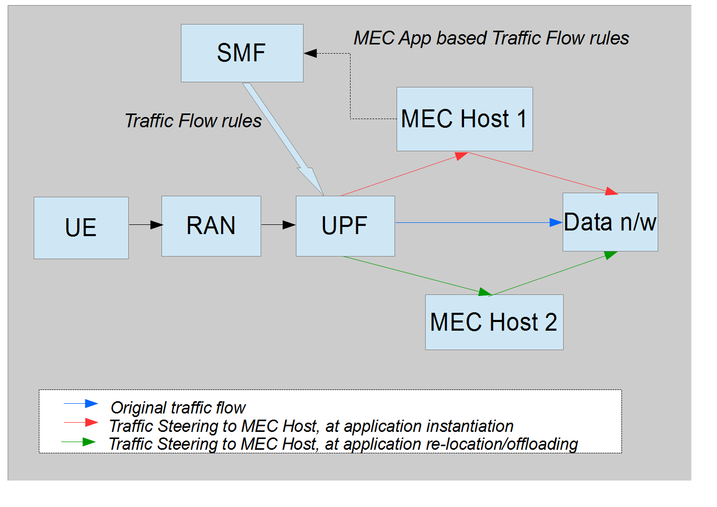 Fig 1: Problem Statement
These inherent capabilities in 5G pave way for successful integration with MEC deployments. Though the 5G 3GPP specifications explain how the 5G core network functions interact with each other and allow external application functions to access them, a complete flow between MEC FEs and the 5G core network functions is missing. MEC FEs need a mechanism to feed the traffic rules (based on UE app requirements) to the SMF. For this, the MEC FEs need to detect the SMF serving the UE. They also need to discover when the selected MEC host becomes non-optimal due to UE mobility and trigger traffic rules update due to application offloading to a new optimal MEC host. The rest of this post digs into some of these issues and explains the interactions between the participating entities during the complete application lifecycle.
The application lifecycle is divided into three stages — application instantiation on the selected MEC host, application migration to a new MEC host due to UE mobility, and application termination. Prior to application instantiation, some UE context is saved in 5G core network as part of UE registration and PDU session establishment. This contextual information is required to choose the MEC host for instantiating the application instance or moving it to a new MEC host on location updates from the core network.
Before Application Instantiation
To trigger application instantiation on a MEC host or to connect to any services towards the core, the UE needs to undergo registration and establish user context with the core network, establish a signaling connection with the AMF, and finally PDU session establishment with the DN via SMF, as shown in Fig 2. SMF selects a UPF for the UE and configures the traffic rules to steer traffic from the chosen UPF to the local DN, as per the subscription information obtained in UE registration stage. This is when the UE can send PDUs to the DN. UE registration and PDU session establishment are explained in more detail in Appendix A.3: (UE Registration and PDU session establishment in 5G).
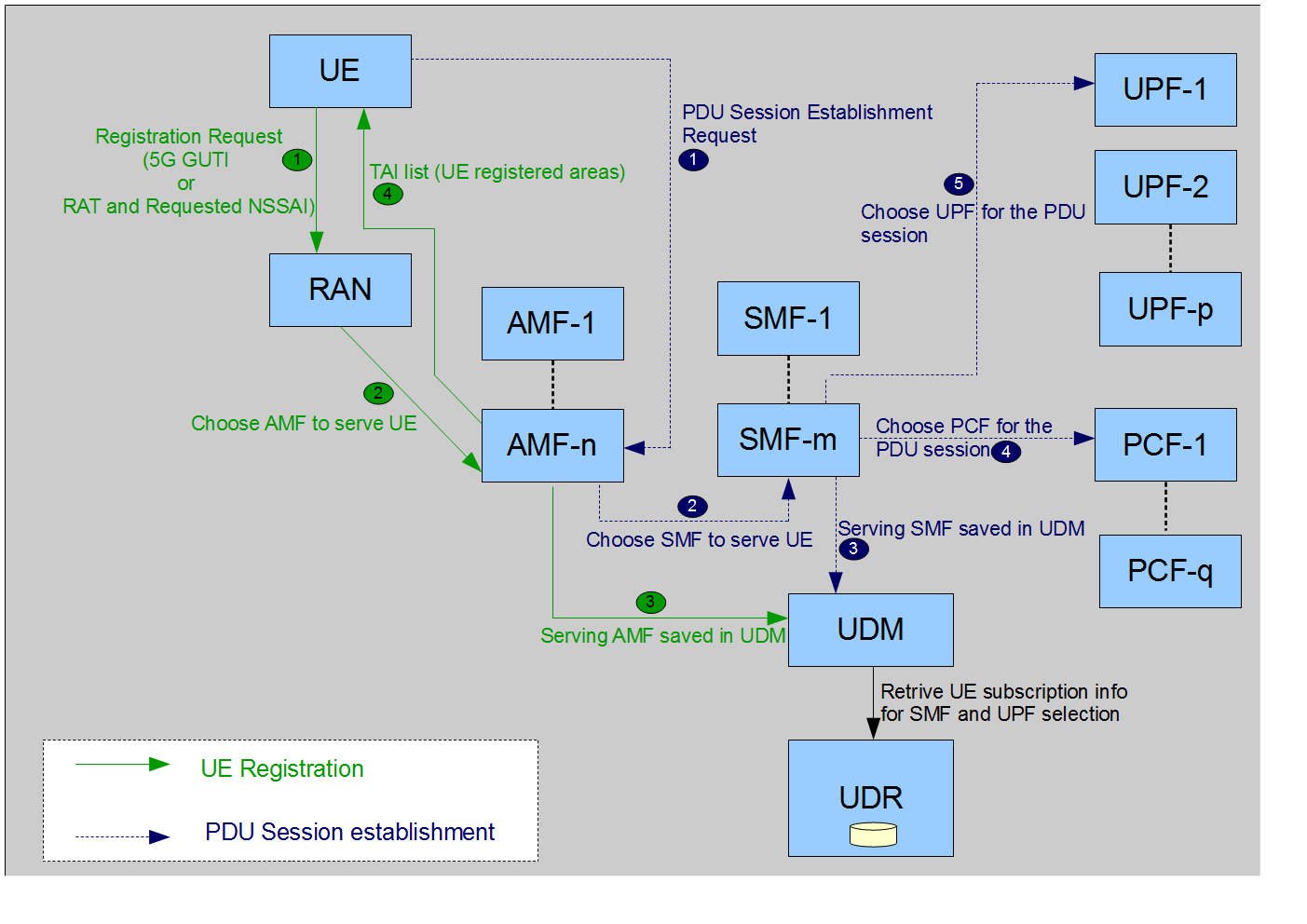
Fig 2: 5G CN procedures before MEC App initiation
Post UE registration, the AMF, serving the UE in the access network through which the UE is registered, is saved in the UDM. The serving AMF registers itself to receive location updates for the UE from the RAN. This serving AMF also handles the mobility registration updates from the UE in case the cell serving the UE is not in the TAI list (tracking area list) received as part of UE registration.
Similarly, the SMF chosen for PDU session establishment is saved in the UDM. This serving SMF registers for location updates of the UE, from the serving AMF. The NEF or PCF can retrieve the serving SMF details from the UDM to feed the traffic rules on application instantiation and relocation, as explained in later parts of this post.
Application Instantiation on MEC Host
MEC functional entities are typically divided into two parts – MEC system-level entities (which comprises of User app LCM proxy, OSS and MEO) lying towards the core network and the MEC host level entities (which comprises of the actual Mobile edge host deployed close to the UEs and the Mobile edge platform). Once the PDU session is established, the UE can trigger the application instantiation on the MEC system.
Prior to application instantiation, the application package needs to be on-boarded to the MEC system. Two alternatives exist for this – either the application provider onboard the application package to the MEO via OSS(clause 5.2.2 of [5]) or theappPackageSource URI (URI of the application package ) is provided to the UE application (by the application provider) and then the UE application passes this URI to the OSS when sending a request to instantiate the application (clause 5.1.3 and 6.2.3 of [9]). The OSS can trigger the onboarding of the package using this URI.
Once the application package corresponding to the desired UE application is on-boarded and enabled on the MEO, the UE can send "Instantiate App” or “application context create” request to the MEO via User app LCM proxy. The onboard application package contains an application descriptor (AppD) specifying the application requirements and desired traffic steering rules. These traffic steering rules comprise of traffic filters to identify the packets, actions to be taken, and the destination interface to receive the packets.
MEO chooses the optimal MEC host (based on constraints, such as latency, available resources, and available services) to service this request. But to trigger traffic steering towards the optimal MEC host, the MEO needs a mechanism to interface with 5G core network functions, as depicted in Fig 3.
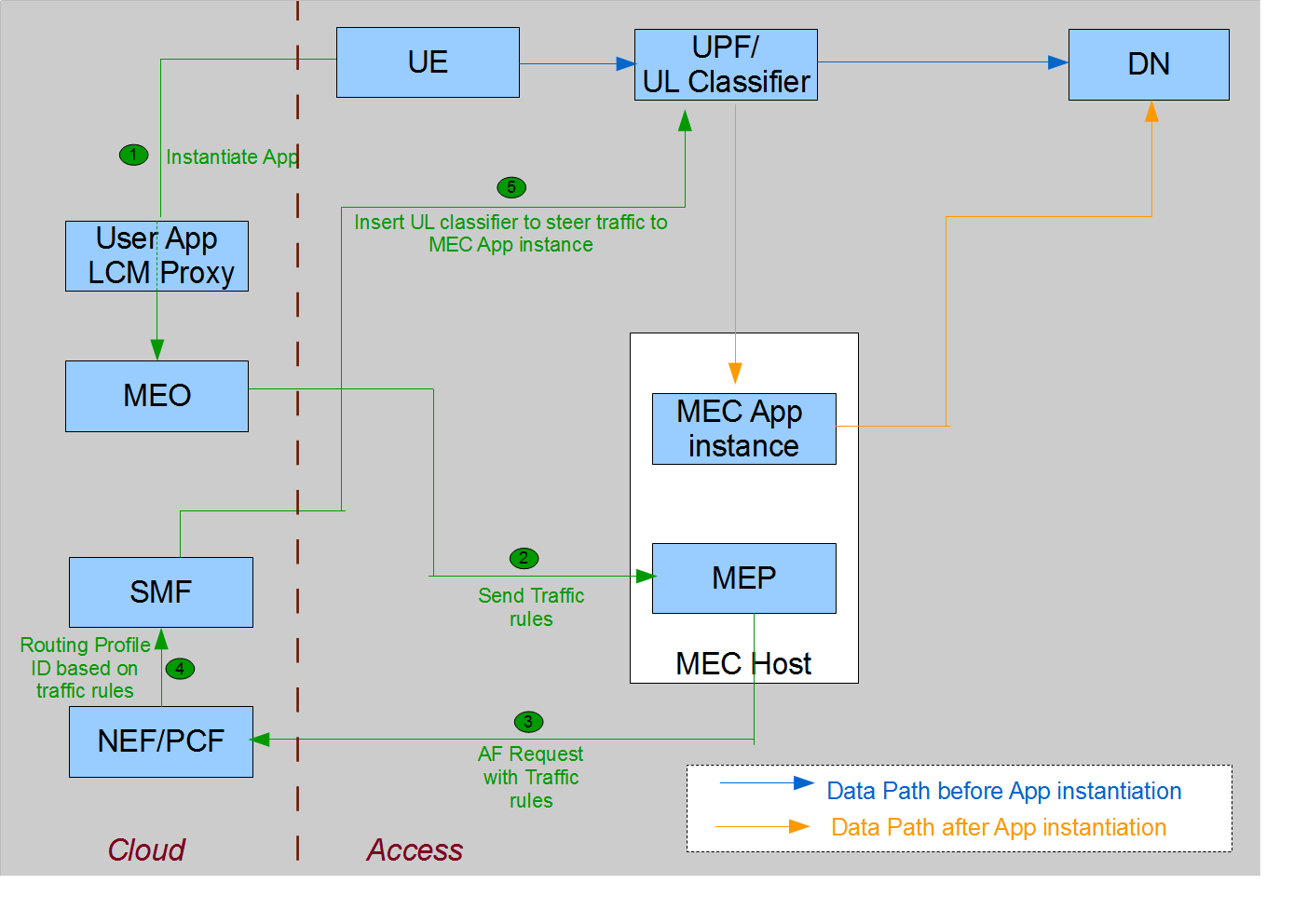 Fig 3: 5G CN procedures at MEC App initiation
Traffic Steering to the MEC Host
The application descriptor AppD in an application package contains the traffic rules required for the data packets to reach the MEC app instance running on a MEC host. MEO obtains this application descriptor when the application package is onboarded. As part of handling the application instantiation or context creation, MEO passes the traffic steering rules in this application descriptor to the MEP of the chosen MEC host.
The MEP acts as an “application function” and interacts with the 5GC via NEF. The MEP triggers an HTTP POST AF request (clause 4.4.7 of [6] Procedures for Traffic Influence) towards NEF. For the 5GC to identify the UE and perform the appropriate traffic steering, the application function request (AF request) from MEP to NEF contains the following information:
- UE identity in terms of GPSI or Ipv4/v6 address
- Traffic descriptions – traffic filters, DNN, and S-NSSAI – to classify the data packets belonging to an application
- Traffic route information – N6 traffic routing information or the routing profile ID preconfigured with the 5GC, specifying the chosen MEC host and interface to receive traffic. This route information identifies the IPv6 address of Data Network in which the chosen MEC host is deployed and the UDP port number of N6 tunnel end of this MEC host in the Data Network
The traffic steering rules retrieved from the AppD (in the application package) and N6 interface information corresponding to the chosen MEC host are used to fill the traffic description and traffic routing information of this AF request. The TrafficInfluSub data model in [6] clearly defines the complete AF request format. NEF is responsible for mapping the information provided by the AF request from the MEP into information needed by the 5GC and passing this information to the PCF.
PCF takes the received AF request and identifies the corresponding routing profile Id (specifying the PCC rules). These routing profile IDs may be pre-configured between the 5GC and AF. In that case, the AF request may pass these routing profile IDs instead of N6 traffic routing information. These IDs are also pre-configured on SMF. PCF passes the selected policy/profile ID to the SMF. SMF accordingly configures the traffic rules on the UPF serving the UE.
To configure these MEC-triggered traffic steering rules on the UPF, SMF configures a UL classifier, which is inserted in the data path of the UE. The traffic steering rules ultimately get installed on this UL classifier. The UL classifier classifies the data packets of the application based on “traffic descriptions” fields and forwards them to the chosen MEC host based on the “traffic route” information of the traffic steering rules.
Location Updates From the 5G CN
In the 5G CN, AMF is responsible for monitoring the UE locations and sending location update notifications (UE mobility event notifications) to the interested entities. AMF has multiple ways to identify that UE location has been updated:
- AMF may request the RAN for location reporting – the RAN shall then send a Location Report message to AMF including UE's last known location with a time stamp. AMF can request continuous reporting mode to get periodic updates. Or it might request “Area of Interest (list of TAIs as per UE registration) based reporting”. In that case, RAN can send a notification to AMF if the RAN detects that the UE presence in the Area of Interest is different from the last one reported.
- The UE is passed a list of TAI in registration response. In case the UE detects that the cell serving the UE is not in this list, it can trigger “Mobility Registration update” with AMF.
With service-based architecture in 5G, AMF offers UE mobility event notification to other services or network functions which act as consumers. Any NF consumer (SMF, PCF or NEF) can subscribe to the AMF, to receive notifications which report a change of ‘UE presence’ in an ‘Area of Interest’. AMF tracks the UE location and determines the ‘UE presence’ in the ‘Area of Interest’. Upon detecting the change, the AMF notifies the new UE location to the subscribed NF consumer (SMF or NEF).
If the SMF subscribes to AMF to receive a notification when AMF detects a change in UE location with respect to Area of Interest, the AMF notifies the SMF about any change in DNAI. The SMF can further trigger user plane management events towards AF or 5G NF (NEF) subscribed to these events.
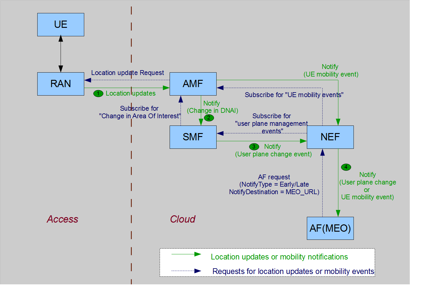
Fig 4: Location updates and mobility events to MEC FE
To get these notifications at the MEC functional entities, the MEO can act as an AF and subscribe to the NEF, as shown in Fig 4 above. The “TrafficInfluSub” [6] field in the AF request from MEO to NEF defines parameters to register a subscription for notifications about user plane management events, with the NEF. One of the parameter is notificationDestination — this contains the Callback URL to receive the notification from the NEF. MEO can include its own URL asnotificationDestination. Whenever the NEF receives a user plane management event notification from SMF, NEF sends an HTTP post message including the notified event to the MEO. Similarly, the NEF can subscribe for UE mobility events directly from the AMF, using the MEO URL as Notification address.
Application Offloading to a New MEC Host
On getting the new UE location (via UE mobility event or user plane management event), the MEO checks if the new area to which the UE moved, is served by same MEC host. If not, MEO needs to relocate the application instance from the old MEC host to the new MEC host serving the current location of the UE. In case the application is stateless, no UE state information is required on the new MEC host. But for stateful applications, the system requires a UE context transfer to support the service continuity to the UE. This context information may be stored in the UE app or app instance in the previous MEC host. This application instance relocation will also trigger traffic steering updates to send traffic to the new MEC host [8]. The MEC system and 5G CN interactions for this traffic steering update are depicted in Fig. 5 below:
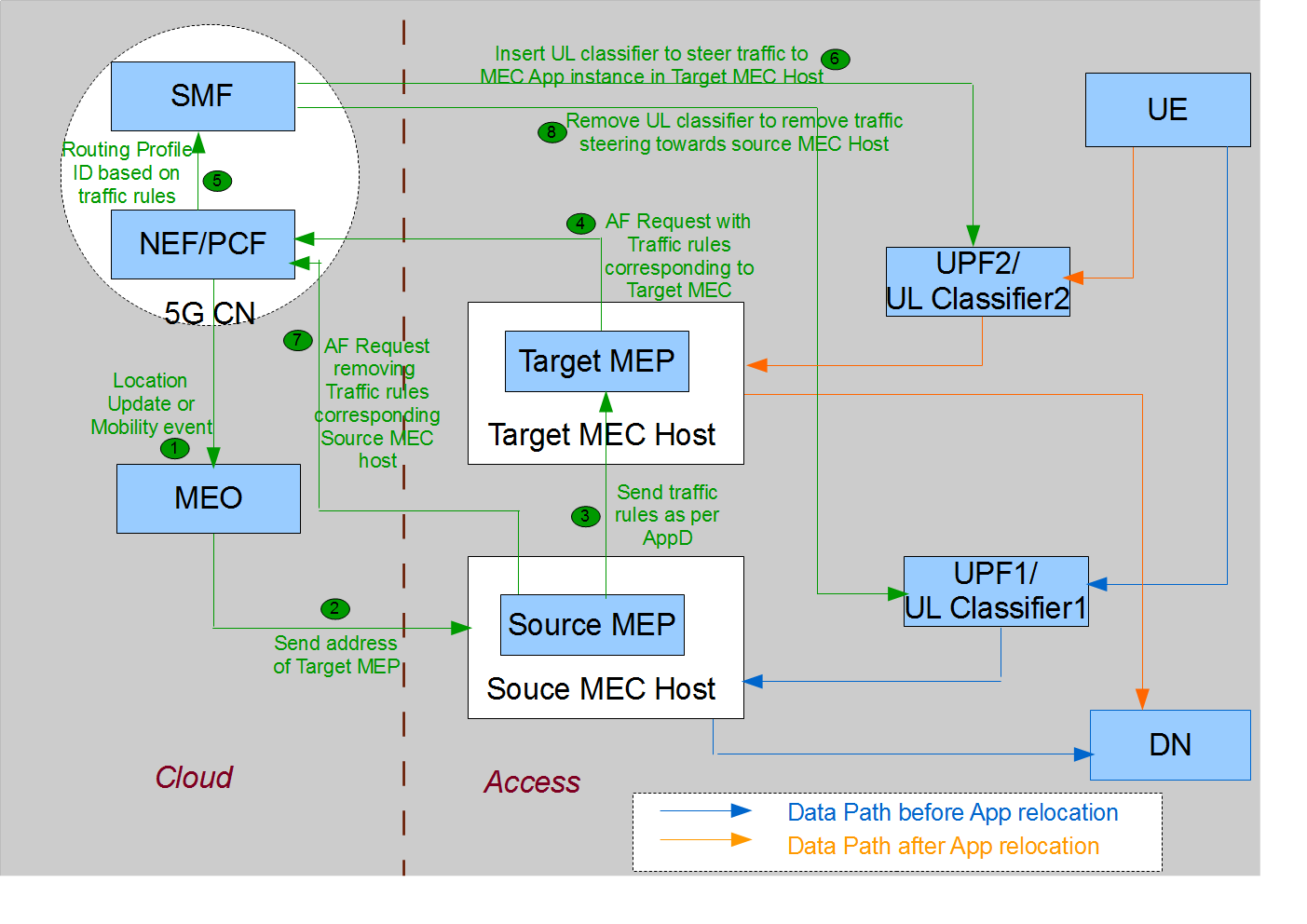
Fig 5: 5G CN procedures at MEC App relocation
MEO passes the address of the target MEP to the source MEP as part of its application relocation procedures. The source MEP passes the traffic steering rules of the application to the target MEP. The target MEP acts as 5G AF to trigger AF request towards the NEF, specifying this target MEC host as a destination in the N6 traffic routing information. NEF passes this new request to PCF. PCF will trigger the updated rules towards the SMF and SMF will insert a new UL classifier in the current data path of the UE. This UL classifier will steer packets towards the target MEC host.
Once the latest rules have been configured to send packets to target MEC host, the source MEP can also send AF request to remove the previously configured traffic steering rules.
Summary
This document elucidates the close interaction between the 5G core network entities and the MEC functional entities on instantiation of UE application on the MEC edge hosts. It also tries to elicit the procedural flow between these entities due to application relocations triggered by UE mobility.
Appendix A.1 (Introducing 5G Core Network Functions Entities)
The 3GPP 5G system architecture [1] explains all the network functions in detail. Fig 6 shows how these network functions replace the 4G EPC functions. Though all network functions have a certain role in UE application initiation and offloading, but for better understanding of this paper, Table 2 enlists the functions that are crucial to know.
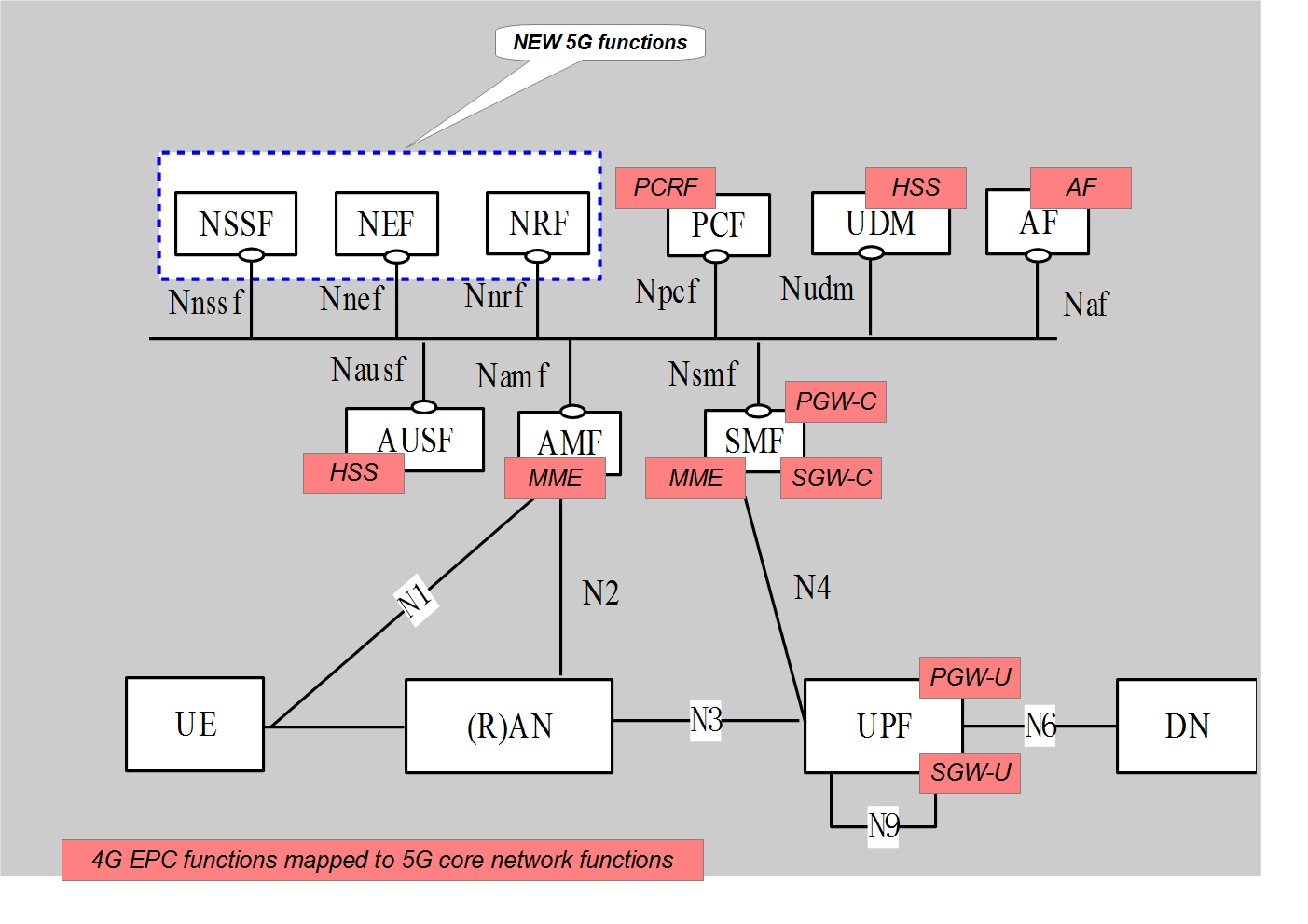
Fig 6: Mapping 4G EPC functions and 5G core network functions
5G CN functions |
Mapping to 4G EPC |
Functions |
Access and Mobility Management Function (AMF) |
MME - Mobility management |
a. Handles the UE registration (initial/periodic/mobility triggered) |
Session Management Function (SMF) |
MME - Session management |
a. Establishment/termination of PDU session between UE and data network (DN) |
User Plane Function (UPF) |
User traffic transport functions of S-GW and P-GW |
a. External PDU Session point of interconnect to Data Network. |
Network Exposure Function (NEF) |
Not present |
a. Expose capabilities and events of 5G core network functions to external entities (not trusted by the operator to have direct access to 5G core network functions) |
Application Function (AF) |
Application Function (AF) |
a. Network functions external to 5G core network and uses these 5G core network functions |
Policy Control Function (PCF) |
PCRF |
a. Handle the application function’s request for traffic steering and map it to the traffic steering policies that SMF understands |
Network Repository Function (NRF) |
Not present |
a. Maintain profiles for instances of the 5G core network functions in terms of type, PLMN Id, FQDN or IP address. |
Unified Data Management (UDM) |
HSS |
a. Provides the UE subscription data and user-context |
Unified data repository (UDR) |
HSS |
a. Stores the UE subscription data to be accessed by UDM |
Table 2: Introducing 5G core network functions
Appendix A.2 (Introducing the MEC Functional Entities)
MEC specification [3] released by ETSI shows the framework and reference architecture for multi-access edge computing needed for running the edge applications in a mobile network. Table 3 mentions the functional blocks from the MEC reference architecture, which are relevant for the understanding of this post.
MEC Functional Entity |
Functions |
UE app |
a. Application running in a UE device. |
User app LCM proxy |
a. Acts as an interface between the UE app and the MEC system-level entities. All UE requests to retrieve the already running app instances on MEC hosts or to trigger application onboarding/instantiations are authorized by the User app LCM proxy and passed further to the MEC system for action. |
Mobile edge host (MEC Host) |
a. Edge host in the Local Area Data Network (LADN) of the UE |
Mobile edge orchestrator (MEO) |
a. Decides the specific MEC host for a UE, from all available MEC hosts in the LADN of the UE |
Mobile edge applications (MEC apps) |
a. Applications running in the MEC host to handle user traffic |
Mobile edge platform (MEP) |
a. Helps in the configuration of the data plane to steer traffic to/from MEC apps as per traffic rules requirements of the UE app |
Table 3: Introducing MEC functional Blocks
Appendix A.3: (UE Registration and PDU Session Establishment in 5G)
The registration request from the UE to RAN contains the 5G-GUTI (Globally Unique Temporary Identifier) assigned to the UE by the PLMN. This 5G-GUTI comprises of GUAMI (Globally unique AMF ID) and 5G-TMSI. The RAN selects the AMF to serve this UE based on the AMF ID identified by the GUAMI. In case 5G-GUTI is not available, it can select AMF based on RAT and requested NSSAI in the registration request. On successful registration, the serving AMF-ID is registered against the UE in UDM and the UE receives a list of TAI (tracking area identity). These tracking areas serve as registration areas of the UE. At any point of time, if the cell serving the UE is not in this TAI list, the UE initiates mobility registration update – this triggers mobility events in the 5G core network.
Post-successful registration, the UE establishes a signaling connection to the AMF to exchange the NAS signaling messages (PDU Session establishment from UE to the SMF, via the AMF). The AMF also selects the SMF that will manage the PDU session between the UE and the DN. AMF can retrieve the list of available SMF instances from the NRF or can use information locally configured on the AMF. The SMF is selected based on the DNN (data network name), S-NSSAI, subscription information of the UE stored in the UDM/UDR, operator policies as well as load conditions of the SMF instances. This serving SMF for UE's PDU Session is also stored in the UDM.
The SMF, as part of session management, selects the UPF to handle the PDU session data traffic. The PDU session establishment request contains the DNN and S-NSSAI. SMF sends DNN, S-NSSAI, and SMF area identity to the NRF. In return, the NRF returns the IP address or the FQDN of the UPF instances available. SMF selects one UPF out of these instances based on the load conditions of UPF instances, UPF location, UE location, UE subscription info in the UDM/UDR, etc.
Based on the DNN and the operator policies, SMF also selects a PCF for this PDU session [4]. The PCF retrieves the policies from the UDR and passes these traffic handling policies to the SMF, which finally passes them to UPF.
References
[1] 3GPP TS 23.501: "System Architecture for the 5G System; Stage 2 (Release 15)".
[2] 3GPP TS 23.502: "Procedures for the 5G System; Stage 2 (Release 15)".
[3] ETSI GS MEC 003: "Mobile-Edge Computing (MEC); Framework and Reference Architecture".
[4] 3GPP TS 23.503: "Policy and Charging Control Framework for the 5G System; Stage 2 (Release 15)".
[5] ETSI GS MEC 010-2 V1.1.1 (2017-07): "Mobile Edge Management; Part 2: Application lifecycle, rules and requirements management".
[6] ETSI TS 129 522 V15.0.0 (2018-07): "5G; 5G System; Network Exposure Function Northbound APIs; Stage 3 (3GPP TS 29.522 version 15.0.0 Release 15)".
[7] ETSI White Paper No. 28: “MEC in 5G networks”
[8] ETSI GR MEC 018: "Mobile Edge Computing (MEC); End to End Mobility Aspects".
[9] ETSI GS MEC 016 V1.1.1 (2017-09): " Mobile Edge Computing (MEC); UE application interface".
Opinions expressed by DZone contributors are their own.

Comments