Data Distribution in Apache Ignite
An excellent primer for distributed data in Ignite.
Join the DZone community and get the full member experience.
Join For FreeThis blog is an abridged version of the talk that I gave at the Apache Ignite community meetup. You can download the slides that I presented at the meetup here. In the talk, I explain how data in Apache Ignite is distributed.
Why Do You Need to Distribute Anything at all?
Inevitably, the evolution of a system that requires data storage and processing reaches a threshold. Either too much data is accumulated, so the data simply does not fit into the storage device, or the load increases so rapidly that a single server cannot manage the number of queries. Both scenarios happen frequently.
Usually, in such situations, two solutions come in handy—sharding the data storage or migrating to a distributed database. The solutions have features in common. The most frequently used feature uses a set of nodes to manage data. Throughout this post, I will refer to the set of nodes as “topology.”
The problem of data distribution among the nodes of the topology can be described in regard to the set of requirements that the distribution must comply with:
- Algorithm. The algorithm allows the topology nodes and front-end applications to discover unambiguously on which node or nodes an object (or key) is located.
- Distribution uniformity. The more uniform the data distribution is among the nodes, the more uniform the workloads on the nodes is. Here, I assume that the nodes have approximately equal resources.
- Minimal disruption. If the topology is changed because of a node failure, the changes in distribution should affect only the data that is on the failed node. It should also be noted that, if a node is added to the topology, no data swap should occur among the nodes that are already present in the topology.
Naive Approach
The first two requirements above are relatively easy to achieve. The most frequently used approach, which is often applied by load balancing among functionally equivalent servers, is modulo N division. Here, N is the number of nodes in the topology. So, we have a one-to-one mapping between the number of the node and the node’s identifier. Then, all we need to do is to represent the object key as a numerical value (by using a hash function) and take the remainder of the division of the obtained value by N.
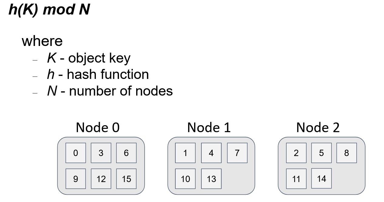
This figure shows the distribution of 16 keys among 3 nodes. The distribution is uniform, and the algorithm to get the node for the object is simple. If any node within the topology uses the same algorithm, then for any given key and N, every node gets the same result.
But, what happens if we introduce a fourth node into the topology?
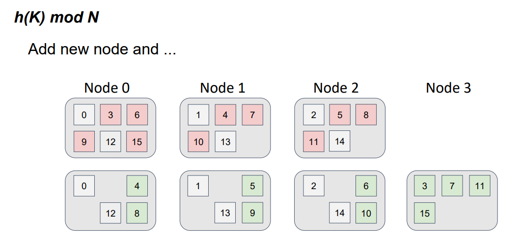
Our function has changed. Now, we divide by 4, not by 3, and take the remainder. Note that, if the function changes, then the distribution also changes.
The object positions for the three-node topology are shown in red, and the object positions for the four-node topology are shown in green. This color schema resembles a file-diff operation. But, in this case, we have nodes, instead of files. It is easy to see that not only did the data move to a new node but also a data swap occurred between the nodes that were in the topology. In other words, we detect parasitic traffic among the nodes, and the requirement of minimal disruption isn't satisfied.
Two ways to solve the data-distribution problem, considering the described requirements, are the following:
- Consistent hashing
- Highest random weight (HRW) algorithm, also known as rendezvous hashing
Both of the algorithms are simple. Their descriptions in Wikipedia require only a couple of lines each. The descriptions make it easy to think of the algorithms as trivial. However, you may find the following papers thought-provoking: Consistent Hashing and Random Trees: Distributed Caching Protocols for Relieving Hot Spots on the World Wide Web and A Name-Based Mapping Scheme for Rendezvous. I think that the most intuitive explanation of the consistent-hashing algorithm is presented in this Stanford course.
Let’s consider the algorithms in more detail.
Consistent Hashing
The basic idea behind the consistent-hashing algorithm is mapping of the nodes and the stored objects on a shared identifier space. So, we make seemingly heterogeneous entities (objects and nodes) comparable.
To obtain such mapping, we apply to the object keys the same hash function that we apply to the node identifier. Denoting the hash function result for a node as “token” will be handy later. We represent our identifier space as a circle; that is, we assume that the minimum identifier value directly follows the maximum identifier value. Then, to identify the node on which the object lives, we need to get the hash function value from the object’s key and trace the circle clockwise, until we hit upon a node’s token. The tracing direction is irrelevant, but the direction must remain fixed.
Imaginary clockwise tracing is functionally equivalent to a binary search over an array of sorted node tokens.
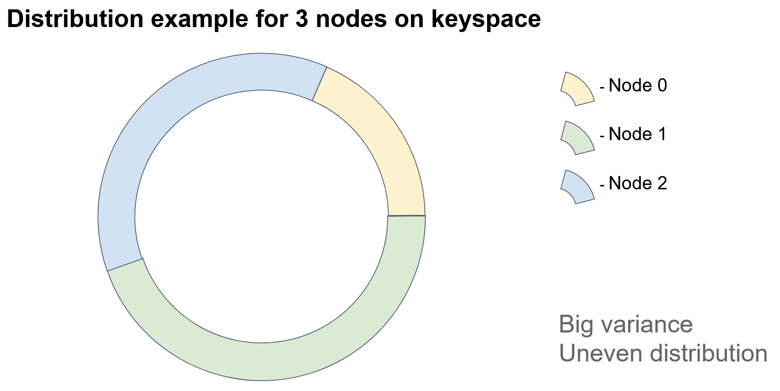
In the diagram, each colored sector represents an identifier space for which a particular node is responsible.
If we add a node, then…
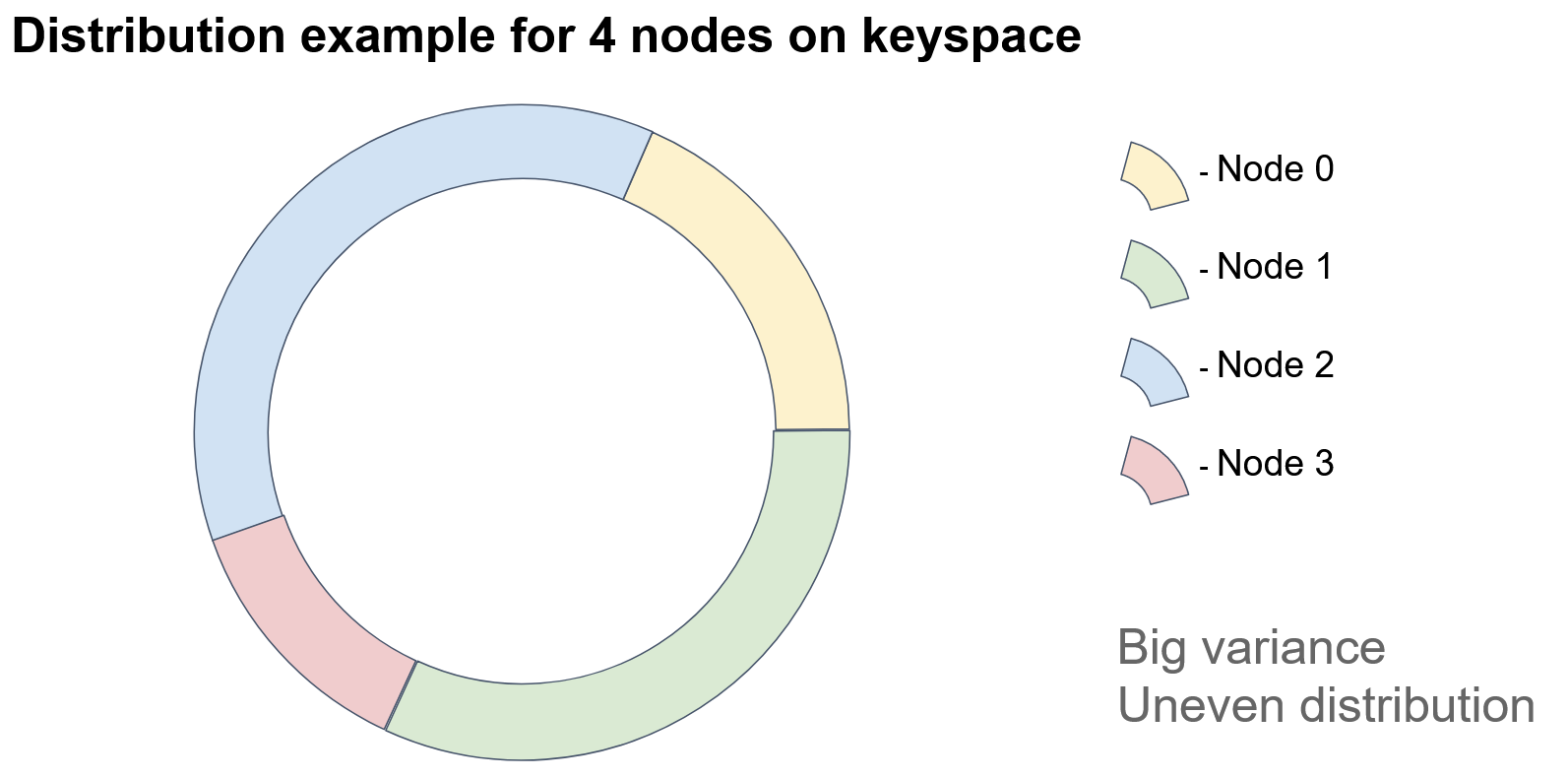
… one of the sectors is split into two parts, and the added node acquires the keys of one of the parts.
In this example, Node 3 acquired some of the keys of Node 1. As you see, because this approach depends heavily on the identifiers of the nodes, it appears that the objects are unevenly distributed among the nodes. How could we improve this approach?
We could assign not one but many (typically, hundreds) of tokens per node. For example, we could introduce a set of hash functions for each node (one per token), or we could recursively apply a single hash function to a token and collect the results of each nesting level. But, be mindful of collisions. No two nodes should have the same tokens.
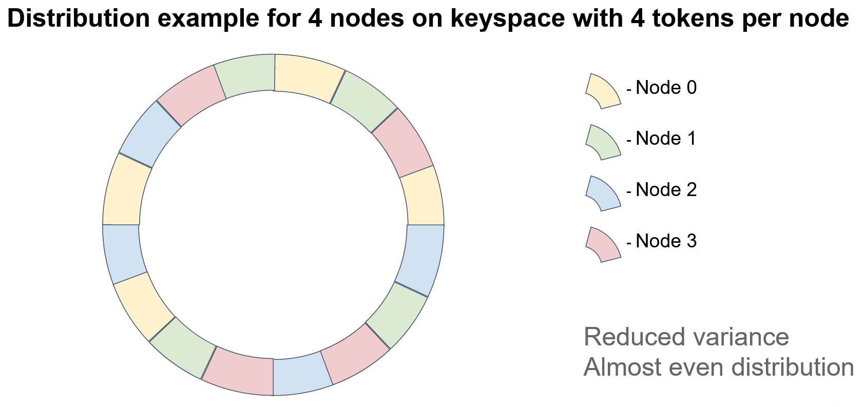
In this example, each node has 4 tokens. Note that, if we want to ensure data integrity, we must store the keys on several nodes (thus, creating “replicas” or “backups”). In the case of consistent hashing, the next N-1 nodes on the circle act as replicas, where N is the replication factor. Surely, node order should be defined relative to a specified token (for example, the first token) because, when multiple tokens are used on each node, the sequence of node positions may differ. Consider the diagram: There is no clear pattern of node repetition.
The minimal disruption requirement for topology modifications is satisfied because the node ordering on the circle remains fixed; that is, the deletion of a node doesn't affect the order of the remaining nodes.
Rendezvous Hashing
The rendezvous hashing algorithm seems to be simpler than the consistent-hashing algorithm. The underlying principle of rendezvous hashing is ordering stability, as was true in the previous case. But, instead of making nodes and objects comparable to each other, we ensure node comparability for only a specified object; that is, we define node ordering for each object independently.
Again, hashing comes to the rescue. But, now, to define the weight of node N for object O, we mix the object identifier and the node identifier and create a hash from the mix. After we perform this process with each node, we obtain a set of weights, according to which we sort the nodes. The node that turns out to be the first node is responsible for storing the key. Because all the nodes in the topology use the same input data, the nodes have identical results. Therefore, the first requirement is satisfied.
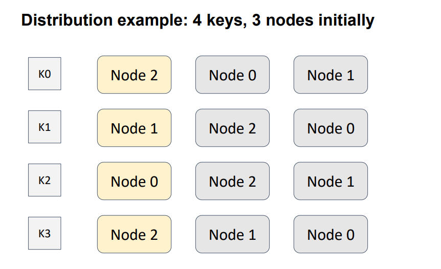
In the 4-node, 3-key example, an order is defined between three nodes for four keys. Yellow indicates the node with the highest weight; that is, the node that will be responsible for a particular key.
Let’s add another node to the topology.
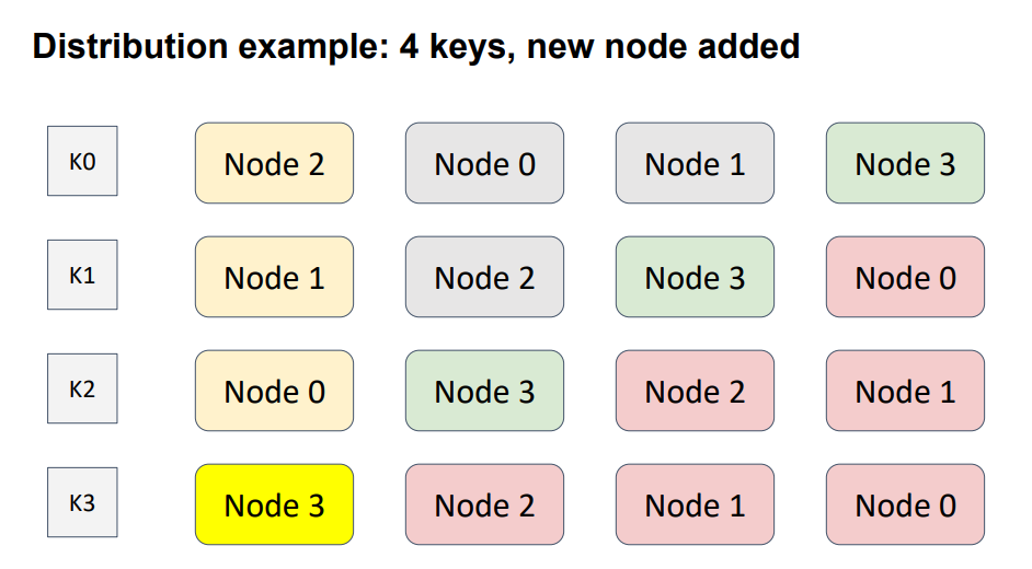
I intentionally put Node 3 diagonally, to cover all possible cases. Here, Node 3, shown in green, was added to the topology. Hence, the node-weight distribution for every key has changed. The nodes shown in red are the nodes that have changed position. The weights of the red nodes are less then the weights of the added node. Therefore, this modification affected only one key, K3.
Let’s extract a node from the topology.
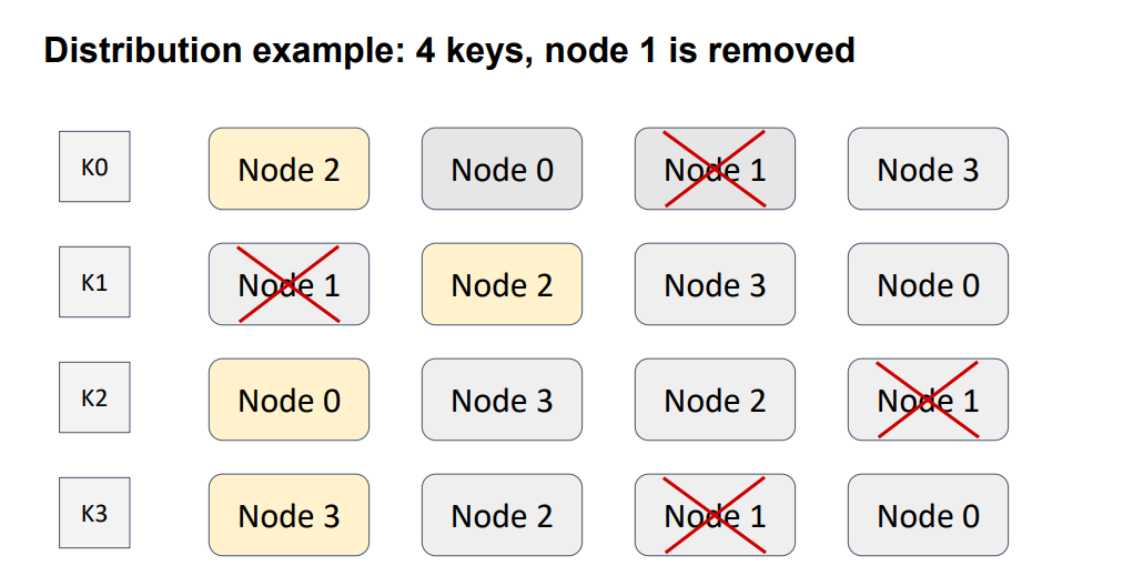
Again, the modification affected only one key, this time K1. The other key remained safe because, as with consistent hashing, the ordering relations in every couple of nodes remain unchanged. Therefore, the requirement of minimal disruption is satisfied, and no parasitic traffic occurs between nodes.
In contrast to consistent hashing, the rendezvous-oriented distribution performs well and requires no additional steps, such as tokens. If we support replication, then the next node in the list is the first replica for the object, the node after the first-replica node is the second replica, and so on.
How Rendezvous Hashing Is Employed in Apache Ignite
Data distribution in Apache Ignite is implemented via the affinity function (see the AffinityFunction interface). The default implementation is rendezvous hashing (see the RendezvousAffinityFunction class).
The first thing to be noted is that Apache Ignite does not map the stored objects directly on the topology nodes. Instead, an additional concept, called “partition,” is introduced. A partition is both a container for objects and a replication unit. And, the number of partitions for a cache (equivalent to a traditional-database table) is specified during configuration and doesn’t change during the lifecycle of the cache.
Thus, we can map objects on partitions by using effective division by modulo and map the partitions on the nodes by using rendezvous hashing.

Because the number of partitions per cache is constant, we can calculate the distribution of partitions over the nodes once and cache the result of the calculation, until the topology is modified. Every node calculates the distribution independently, but, if the input data is identical, the distribution is the same. A partition can have several copies, which we call ”backups.” The master partition is called the “primary” partition.
For an optimal distribution of keys over partitions and partitions over nodes, the following rule should be satisfied: The number of partitions should be significantly greater than the number of nodes, and the number of keys should be significantly greater than the number of partitions.
Caches in Ignite can be either partitioned or replicated. In a partitioned cache, the number of backups is specified during cache configuration. The partitions, primary and backup, are uniformly distributed among the nodes. The partitioned cache is suitable for operational data processing because partitioned cache configuration ensures the best write performance, which depends directly on the number of backups. Generally, the more backups, the more nodes that must confirm the key record.
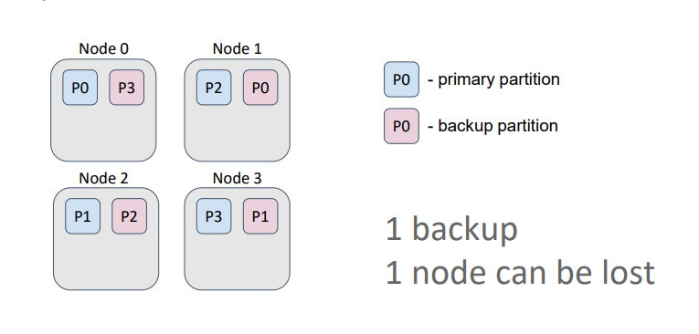
In this example, the cache has one backup. Therefore, even if we lose a node, we retain all the data because a primary partition and its backups are never stored on the same node.
In a replicated cache, the number of backups equals the number of nodes in the topology minus 1. Therefore, each node contains copies of all partitions.
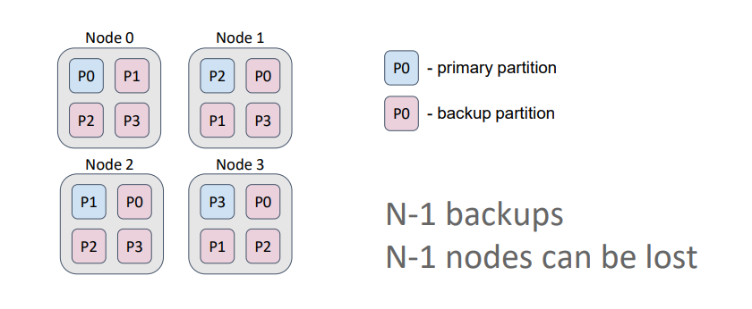
Such a cache is optimal for data that is rarely modified (such as dictionaries) and ensures the highest availability because we can lose N-1 nodes (3 in this case) and still retain all the data. Also, in this setting, if we allow data to be read from primary partitions and from backups, we maximize read performance.
Data Colocation in Apache Ignite
In regard to performance, an important concept is colocation. Essentially, colocation is the positioning of multiple objects in the same place. In our case, the objects are the entities that are stored in the cache, and the place is a node. If the objects are distributed among the partitions via the same affinity function, then the objects, which have the same affinity key, are placed into the same partition and, consequently, into the same node. In Ignite, such an approach is called “affinity-based colocation.” An affinity key is, by default, the primary key of an object. But, Ignite also allows the use of any object field as the affinity key.
Colocation significantly reduces the amount of data that is transferred between nodes for computations or SQL queries. Therefore, colocation minimizes the number of network calls that are required to complete tasks. Let’s consider an example of this concept. Suppose that our data model consists of two entities: order (Order) and order item (Order Item). Multiple order items can correspond to one order. Identifiers of orders and order items are independent from each other, but an order item has an external key, which references the order that corresponds to the order item. Suppose that we need to perform a task that requires calculations on items that belong to the order.
By default, the affinity key is the primary key. Therefore, orders and order items are distributed among nodes according to their primary keys, which are independent.

In this diagram, orders are represented as squares, and order items are represented as circles. The colors denote which item belongs to which order. With such a data distribution, our hypothetical task is sent to the node where the target order resides; then, the task reads order items from all the other nodes or sends a subtask to the nodes and gets the result of the computation. This redundant network interaction can and must be avoided.
What if we give Ignite a cue to place the order items on the nodes that the orders are placed on; that is, we colocate the data? We will choose an external key as the affinity key for an order item, and, further, we will use the chosen object’s field to calculate the partition to which the record belongs. Therefore, we can use our object’s primary key to find our object within the partition.
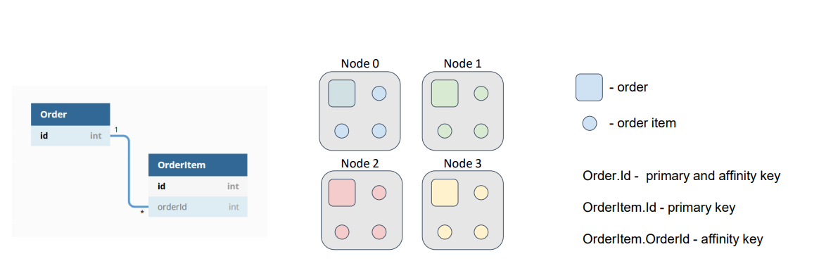
Now, if both caches (Order and OrderItem) use the same affinity function with the same parameters, our data will be colocated, and we won’t need to move around the network, searching for order items.
Affinity Function Configuration in Apache Ignite
In the current implementation, the affinity function is a parameter of cache configuration.
Upon instantiation, the affinity function takes the following arguments:
- Number of partitions
- Number of backups (essentially, this argument is also a cache-configuration parameter)
- Backup filter
- Flag excludeNeighbors
These parameters cannot be changed. During execution, the affinity function takes as input the current cluster topology (essentially, the list of nodes in the cluster) and calculates the distribution of partitions among nodes (as shown in the preceding examples, in the context of the rendezvous-hashing algorithm). Concerning the backup filter which just is the predicate, which can prevent the affinity function from assigning a partition backup to the node for which the predicate returned the value «false».
For example, assume that our physical nodes (servers) are placed in a data center on different racks. Usually, each rack has a dedicated power supply…
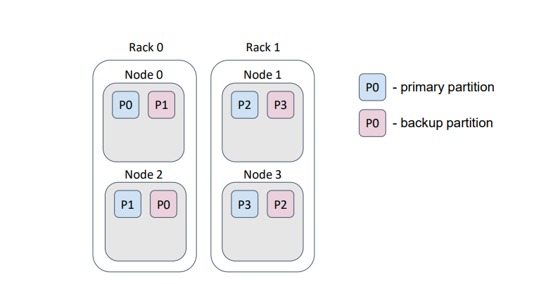
… and, if we lose a rack, we lose the rack’s data.
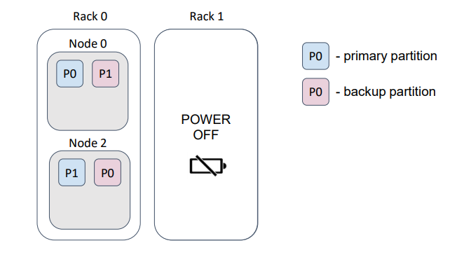
In this example, we lost half of the partitions.
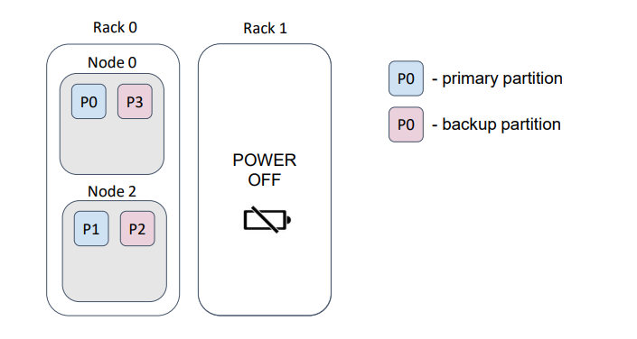
But, if we provide a correct backup filter, then the distribution changes as follows …
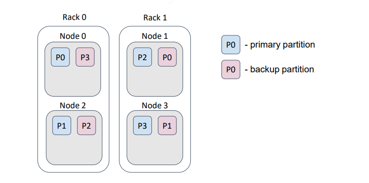
… such that, loss of a rack does not cause loss of data.
The flag excludeNeighbors is functionally similar to the backup filters; it is, essentially, a shortcut for a specific case.
Frequently, several Ignite nodes are deployed on one physical host. This use case is similar to the “racks in the data center” case, but now we prevent the loss of data that results from a host failure.

Such behavior can be implemented with a backup filter. excludeNeighbors flag is a legacy, which can be removed in the next major Ignite release.
Conclusion
In conclusion, consider an example distribution of 16 partitions in a topology of 3 nodes. For the sake of simplicity and illustration, we assume that the partitions have no backups.
I wrote a small test that showed the distribution:
 Notice that the partition distribution is not uniform. But, with an increase in the number of nodes and partitions, the deviation decreases significantly. The most important requirement is to ensure that the number of partitions exceeds the number of nodes. Currently, the default number of partitions in a partitioned Ignite cache is 1024.
Now, let’s add a node to the topology.
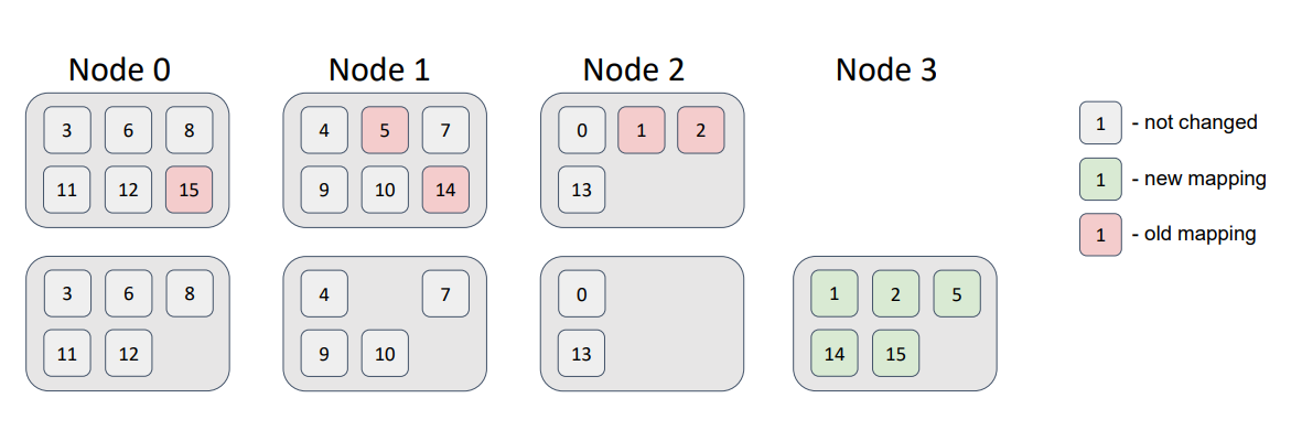
We see that some partitions migrated to the new node. Therefore, the minimal disruption requirement was satisfied; the new node received some partitions; and the other nodes didn’t swap partitions.
Now, let’s delete a node from the topology:
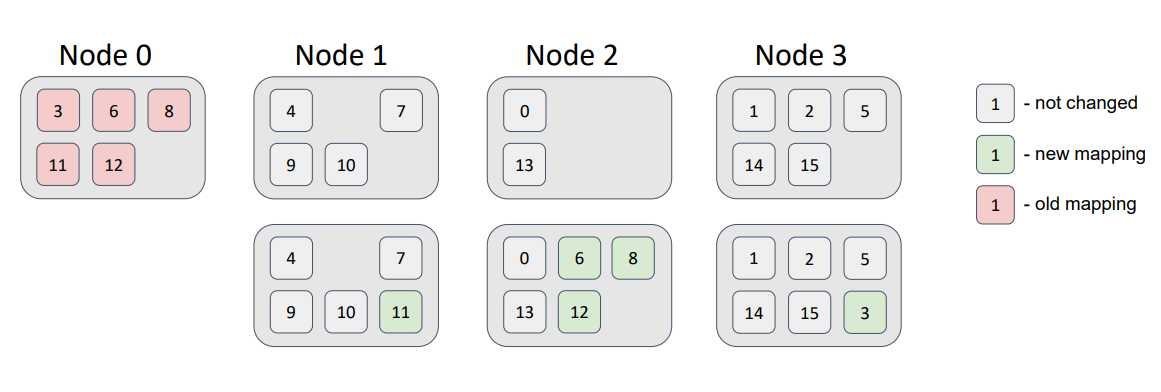
Here, the partitions that were related to Node 0 were distributed among the remaining topology nodes, without violation of the distribution requirements.
As you see, simple methods can solve complex problems. The solutions described in this article are used in most distributed databases. And, they do their job reasonably well. But, the solutions are randomized. Therefore, distribution uniformity is far from perfect. Can we improve uniformity, maintain performance, and meet all distribution requirements? The question remains open.
Published at DZone with permission of Andrey Gura. See the original article here.
Opinions expressed by DZone contributors are their own.

Comments