Two libraries are commonly used for accessing the GPIO pins on the Raspberry Pi: Device I/O and Pi4J. The Device I/O library, which is part of the OpenJDK project, provides a standard library for accessing I/O pins across any embedded platform, including the Raspberry Pi. The Pi4J library is an open-source library that is exclusive to the Raspberry Pi. Here is a quick comparison of the two libraries:
| Open Source |
Yes |
Yes |
| Portable to Java ME |
Yes |
No |
| API Optimized for Java 8 |
Yes |
No |
| Support for New Raspberry Pi Boards |
Lagging |
Excellent |
| Advanced Features |
None |
Button Debouncing, Interrupt-based Listening |
| Extensible Providers for Add-On Boards |
No |
Yes |
| Low-Level GPIO Access |
No |
Yes |
Installing the Device I/O Library
Currently the Device I/O library is not released with the version of Java on the Raspberry Pi. Also, there are no binary builds available, so you have to build the library from source. Fortunately, this is a fairly easy process and can be accomplished directly on the Raspberry Pi.
To start, download the source code from the OpenJDK Mercurial repository by executing the following command from an SSH prompt or the console on your Raspberry Pi:
sudo apt-get install mercurial
Next, clone the Device I/O library source code to your Raspberry Pi. The following command creates a folder called dio in your current working directory with the latest source code:
hg clone http://hg.openjdk.java.net/dio/dev dio
To build the source code, you need to run the make command on the newly downloaded code. The build script also requires a few variables to be set up so it knows where to access the Raspberry Pi native libraries and the Java 8 JDK:
cd dio
export PI_TOOLS=/usr
export JAVA_HOME=/usr/lib/jvm/jdk-8-oracle-arm-vfp-hflt
make
Next, install it into the local Java Runtime Environment (JRE):
sudo cp -r build/deviceio/lib/* $JAVA_HOME/jre/lib
You will also need the libraries locally for your project. To do this you can use any visual Secure Copy (SCP) or Secure FTP (SFTP) client, such as Cyberduck. However, real geeks will do it from the command line (this works out of the box in OS X or Linux). Unlike the other commands, this one must be run from your desktop or laptop that is connected to your Raspberry Pi:
scp pi@timerpi.local:~/dio/build/deviceio/lib/ext/dio.jar dio.jar
Note: Substitute your Pi IP address or hostname for timerpi.local. Also, this command assumes that the dio folder was created in your user home directory on the Raspberry Pi. If not, adjust the path as appropriate.
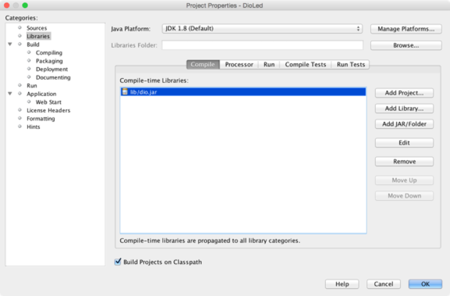
To use the Device I/O library in your project, create a new Java project called DioLed in NetBeans and add dio.jar as a compile-time library. To access the library settings, choose File | Project Properties (DioLed), click Libraries in the Categories pane, and make sure the Compile tab is selected. Then click Add JAR/Folder and choose the dio.jar file you copied over from the Raspberry Pi.
Device I/O Pin Assignments
The Java Device I/O library uses the standard GPIO port assignments as specified by the Motorola Broadcom chipset. The following diagram shows a full list of all the ports, their numbers, and what their functions are for the Raspberry Pi B+, A+, 2, and Zero.
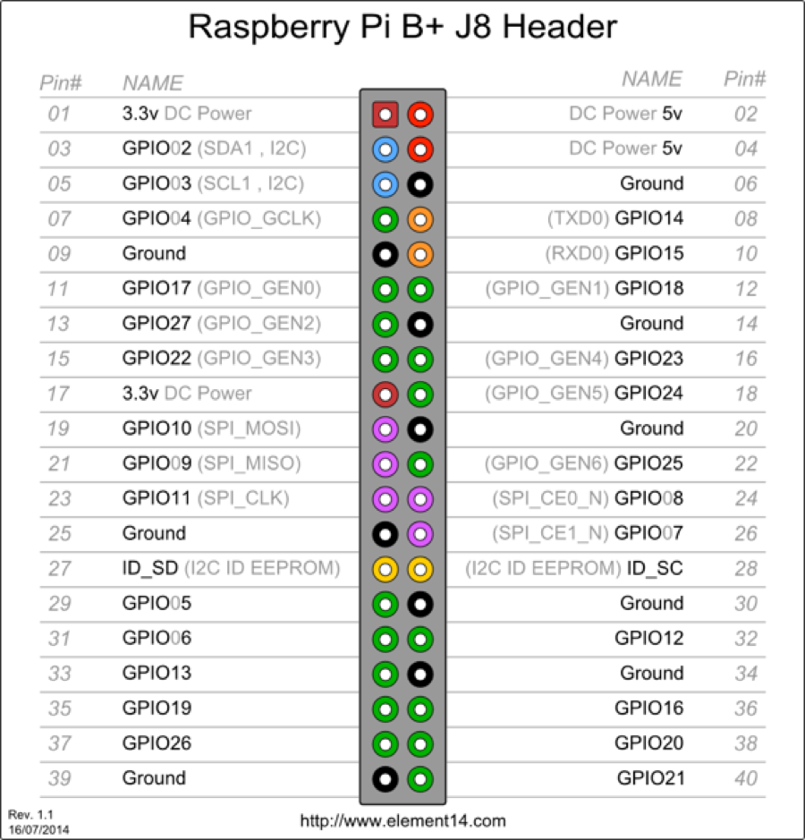
Even though there are 40 pins total, several of them are not usable for GPIO since they supply power (3.3v/5v) or ground. Most of the remaining pins can be used for GPIO, but may require some configuration before they are accessible. Specifically:
- Pins 3 and 5 are for ICBy default, the IC bus is disabled and these pins can be used for GPIO. However, these have hard-wired internal 1.8kΩ pull-up resistors to 3.3V.
- Pins 8 and 10 are for Serial UARTThese pins are reserved for console serial communication by default, which needs to be disabled if you want to use them for GPIO or to connect to a serial device.
- Pins 19, 21, 23, 24, and 26 are for SPIThis is another communication bus for devices that is disabled by default, so these pins can be used for GPIO.
- Pins 27 and 28 are for EEPROMThese pins are designed for identifying add-on boards stacked on top of the Raspberry Pi and can’t be used for GPIO.
Device I/O Library LED Test
To demonstrate how to use the Device I/O library for output, we are going to blink a light-emitting diode (LED). This is a great way to test out your GPIO pins since it is a visible device that can be powered by the current from the pins.
Connecting an LED to the Raspberry Pi GPIO pins just requires a few jumper cables. To prevent the LED from being overloaded, we also need a resistor that we can hook up in serial as shown in the following wiring diagram.
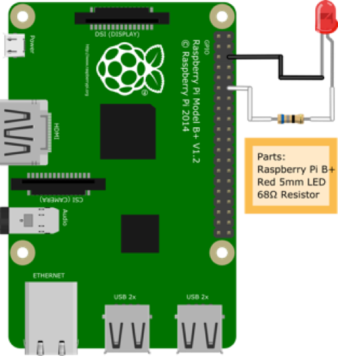
This is a simple circuit with a 68Ω resistor, an LED, and some wires. Note that LEDs have a positive side and a negative side, usually indicated by the positive lead (the anode) being slightly longer than the negative lead (the cathode). If you hook up the LED backward, it won’t damage it, but it won’t light up either, so make sure that you hook up the longer end to the GPIO pin.
To turn this on and off with the Device I/O library, we need to create three files:
- java.policy The policy file that grants permissions for us to use GPIO
- dio.properties Defines the pin setup for our application
- DioLed.java Our main Java code that will blink the LED
The policy file is really a legacy from the Java ME Device I/O API and is intended for highly restricted environments where you want to limit the access to peripherals, such as cell phones. For applications running on small, embedded systems like the Raspberry Pi, you will most often have control of the entire embedded device and not be competing with other applications installed by end users, so a permissive policy file is fine. The following code is a great boilerplate permissions file to use for all your projects.
// grant all permissions for the DIO framework
grant {
    permission jdk.dio.DeviceMgmtPermission "*:*", "open";
    permission jdk.dio.gpio.GPIOPinPermission "*:*", "open,setdirection";
    permission jdk.dio.gpio.GPIOPortPermission "*:*";
    permission jdk.dio.i2cbus.I2CPermission "*:*";
    permission jdk.dio.spibus.SPIPermission "*:*";
    permission jdk.dio.uart.UARTPermission "*:*";
};
The pin configuration file requires a little bit more customization since you will often want to change which pins are used for input/output and possibly add or remove features like serial, I²C, and SPI. You can often take an existing pin configuration file and customize it or pare it down to the features you need. For the simplest cases, it is easy enough to create one from scratch as well. The following code opens a single pin for output.
gpio.GPIOPin = initValue:0, deviceNumber:0, direction:1, mode:4, trigger:3, predefined:true
1 = deviceType: gpio.GPIOPin, pinNumber:18
The first line defines the defaults for the gpio.GPIOPin device type.
Possible constants for direction (dir), mode, and trigger in Device I/O property files are as follows:
DIR_BOTH_INIT_INPUT = 2;
DIR_BOTH_INIT_OUTPUT = 3;
DIR_INPUT_ONLY = 0;
DIR_OUTPUT_ONLY = 1;
MODE_INPUT_PULL_DOWN = 2;
MODE_INPUT_PULL_UP = 1;
MODE_OUTPUT_OPEN_DRAIN = 8;
MODE_OUTPUT_PUSH_PULL = 4;
TRIGGER_BOTH_EDGES = 3;
TRIGGER_BOTH_LEVELS = 6;
TRIGGER_FALLING_EDGE = 1;
TRIGGER_HIGH_LEVEL = 4;
TRIGGER_LOW_LEVEL = 5;
TRIGGER_NONE = 0;
TRIGGER_RISING_EDGE = 2;
There is also a bit of ceremony around how you need to configure your NetBeans project to properly deploy the Device I/O configuration files and refer to them from the run command. To make sure your property and permission files are copied to the output directory, you need to add an extra build post-compile step to your NetBeans build.xml file.
<target name="-post-jar">
    <copy todir="${dist.jar.dir}">
        <fileset dir="config" includes="**"/>
    </copy>
</target>
The ant target assumes that both your java.policy and dio.properties files are in a folder called config under the project root.
Once these files are configured to copy over to the build folder after compilation, you also need to modify the java run command to make use of them. To do this, open the Project Properties dialog, click Run in the Categories pane, and enter the following VM Options:
-Djdk.dio.registry=dist/dio.properties -Djava.security.policy=dist/java.policy
And finally the Java code to turn on and off the LED in a file called DioLed.java.
public class DioLed {
  public static void main(String[] args) throws IOException, InterruptedException {
    try (GPIOPin led = DeviceManager.open(1);) {
      for (int i = 0; i < 10; i++) {
        led.setValue(i % 2 == 0);
        Thread.sleep(500);
      }
    }
  }
}
Notice that this code is fairly clean and succinct. It uses a try-with-resources block to open the GPIOPin as well as automatically close it at the end. The function for setting the LED value is very straightforward as well. One important thing to note is that the GPIO number referenced in the open method is the ID in our dio.properties file, not the Broadcom GPIO number!
Using Pi4J
The Pi4J library is written by Robert Savage and based on the very widely used WiringPi C library. Compared to the Device I/O library, Pi4J has lots of features and is very easy to get started with.
To use Pi4J you just require one JAR file (pi4j-core.jar)—no permissions, no property files, no custom JVM arguments. However, you do require root access for the java process. To run with root from NetBeans, you need to:
- Choose Tools | Java Platforms.
- Click your Raspberry Pi platform under the Remote Java SE tree.
- Click the Exec Prefix field and enter a value of sudo.
Pi4J Pin Assignments
By default, Pi4J uses the WiringPi pin assignments. The advantage of this is that they are sequential and in the same location from revision to revision of the Raspberry Pi boards. In practice this only matters between revisions 1 and 2 of the Raspberry Pi B, because the Raspberry Pi Foundation has standardized on the main header pin layout for all subsequent boards, opting to add more pins to the header instead. Here is a diagram showing the pin assignments to use with Pi4J.
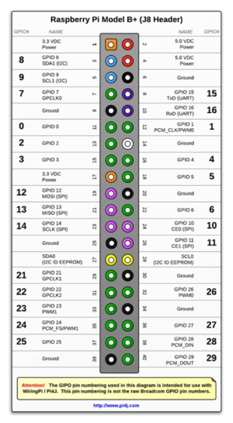
Pi4J also has the option to initialize pin assignments to the Broadcom GPIO pin numbering. However, I don’t recommend changing this, since it will confuse others who are familiar with the Pi4J library and assume certain pin assignments.
Pi4J LED Test
To demonstrate the usage of the Pi4J library, we are going to recode exactly the same LED test using the Pi4J library instead. However, the setup of Pi4J is much simpler and the number of changes is minimal, so this will be a breeze!
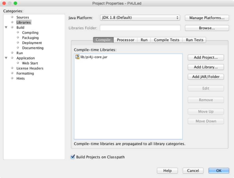
To start, create a new project called Pi4JLed as a Java project type. Open the Project Properties dialog of your new project and go to the Libraries category. Click Add JAR/Folder, and select the pi4j-core.jar file. If you don’t already have this library, you can download it from the Pi4J Project site here: pi4j.com.
Now you can start writing the code for triggering the LED. Here is the same example with an LED blinking five times, coded using Pi4J libraries:
public class Pi4JLed {
  public static void main(String[] args) {
    GpioController gpio = GpioFactory.getInstance();
    GpioPinDigitalOutput led = gpio.provisionDigitalOutputPin(RaspiPin.GPIO_01);
    for (int i = 0; i < 10; i++) {
      led.setState(i % 2 == 0);
      Gpio.delay(500);
    }
    gpio.shutdown();
  }
}
Here are some of the differences that you should take note of:
- There is no try block, because Pi4J doesn’t support auto-closable for use with try-with-resources. However, it does register shutdown hooks for you, so you can be lazy and let it do the work for you.
- Pi4J requires initialization before the use of the first pin. Shutdown is optional, but recommended if you don’t want the system to wait for threads to time out, which can take up to 30 seconds.
- There are no exceptions in the Pi4J version! Pi4J doesn’t throw IOExceptions that we have no idea how to recover from (thankfully!) Also, rather than using Thread.sleep, there are some nice convenience methods for this on the Pi4J GPIO class.
- The GPIO port is the same. Well, this is not a difference, but it is a very important similarity by coincidence. We are referring to Broadcom GPIO port 18 in both cases. This maps to WiringPi port 1 (per the diagram in the previous section), and we also happen to have slotted it into configuration 1 in the dio.properties file. However, don’t rely on ports being the same in general.
And there you have it. You were able to replicate the same LED blinking code using the Pi4J library and have completed your first Raspberry Pi project using two different GPIO libraries.