Manipulate LED RGBW Light Bulbs in .NET
The main goal of this article is to show you how to control the Milight RGBW light bulb using .NET. We'll provide you with the most useful command patterns and explain how this kind of lighting system works. Read on to learn more.
Join the DZone community and get the full member experience.
Join For Freemilight led rgbw light bulbs are a lighting system similar to the phillips hue light bulbs. both work using the same pattern: they can be controlled via a wireless network via software you can write. but, milight are a lot cheaper than hue. milight light bulbs come in two types: white and rgbw (red-green-blue-white). we decided to work with the rgbw version, because it has much more potential than the white-only version and allow us to build more advanced and "case-sensitive" programs like continuous integration signaling tools (more on this later). all of that will be based on this simple steering application that we will create. our goal in this project was to create a .net application that can control this lighting system via wi-fi bridge (wi-fi controller) and ultimately the continuous integration (ci) signaling tool.
how it works?
milight led rgbw are radio controlled light bulbs that use a wi-fi bridge as a "medium" that converts udp packets sent via wi-fi network into radio signal that is readable for the light bulb itself.
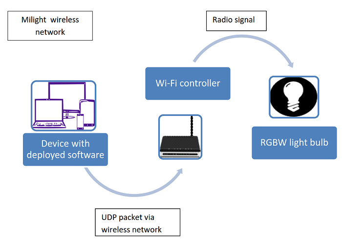
figure 1. rgbw led light bulb architecture.
to execute commands on the lighting system, we need to use udp and send a packet containing 2 byte information to the wi-fi controller. the wi-fi controller will translate it into a radio signal and send it directly to light bulb. every byte is represented by value in 8-bit hexadecimal code (for example 0x00). the light bulb can communicate only in one direction, so it can only react to commands but it is not possible to query its actual state.
we can:
- pair our application with a light bulb
- change the value of the color or brightness
- turn it on and off
setup
figure 1 shows our gear: one milight rgbw light bulb, one milight wifi bridge, and a power cord for the bridge.
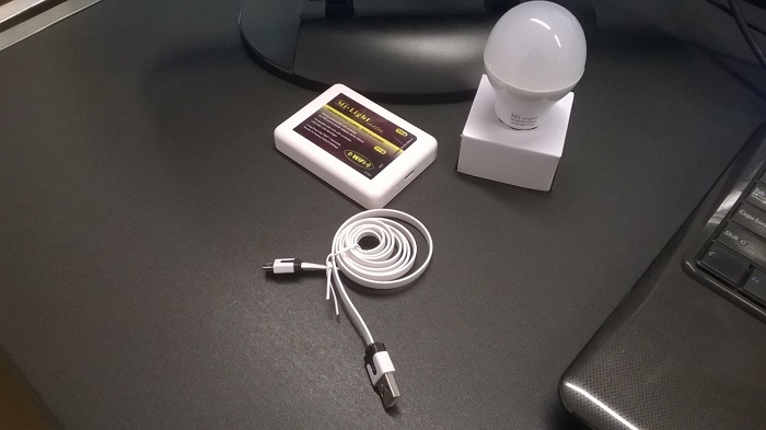
figure 2. complete milight wireless light bulb set with wi-fi controller.
you can connect the setup and use one of the mobile device applications (available on the google play store and the apple store) to steer the light bulb. but, if you want to steer the light using your own software (like we do!), you will need to set the static ip to it. a great article on how to do this can be found here .
in this setup, the bridge provides its own wifi network called milight or milight_"something". you can connect to this network and send the commands to the default gateway.
you can also connect the bridge to your existing wifi network (sta mode). in order to do this, open the browser, go to the default gateway ip, and log on using "admin" as the user name and password. set up your sta mode. in that case, you should know what the command’s ip is.
implementation
to create our application, we used microsoft windows presentation foundation ( wpf ), and for the color picker we used infragistics color picker [1] .
1) sending packets via udp
to transmit udp packets to the wi-fi controller, we created udptransmission class:
 class udptransmission
    {
        private const int port = 8899;

        public static void transmission(byte[] data, string ip)
        {
            var serveradd = ipaddress.parse(ip);
            udpclient udpclient = new udpclient(port);
            udpclient.connect(serveradd, port);
            udpclient.send(data, data.length);
            system.threading.thread.sleep(100);
            udpclient.close();

        }
    }
the udptransmission class contains transmission method with two parameters that accepts only an array of bytes and an ip string. according to the documentation, udp packets need to be sent on port 8899 so it is set as constant. what’s more, every command needs to be sent with a 100 ms delay, so that’s why the thread is put to sleep for a duration of 100 ms. please note that error handling is not provided in order to keep the code examples short.
2) commands, code flex, and readability
for the sake of code readability, every action the light bulb can perform is represented with enum. there are 3 types of enums in this project:
· activities (connect)
· states (on, off)
· discomode (advanced multicolor illumination)
in every command (which contains 2 bytes) one byte is always constant , so in this scenario we can easily attach command byte to the enum that represents the equivalent of the proper action. for example:
public static byte[] states(state state)
        {
            byte statebyte;

            switch (state)
            {
                case state.on:
                    statebyte = 0x42;
                    break;
                case state.off:
                    statebyte = 0x41;
                    break;
                default:
                    throw new indexoutofrangeexception();

            }
            return new byte[] { statebyte, 0x1b };
        }
this structure adds to the code flexibility and makes it more readable for the programmer.
3) pairing application with light bulb
note: our application must be connected to a wireless network created by the milight wi-fi controller to perform pairing and other commands.
before sending any command, our application needs to be paired with the light bulb. we can achieve this by sending an array of 2 bytes, where the first byte is represented by code 0x45 followed by the second byte which is the constant 0x00. a code snippet is shown below. from now on, the light bulb will react to every command.
        public static byte[] activities(activity activity)
        {
            byte activitybyte;

            switch (activity)
            {
                case activity.connect:
                    activitybyte = 0x45;
                    break;
                default:
                    throw new indexoutofrangeexception();
            }

            return new byte[] { activitybyte, 0x00 };
        }
keep in mind that the initial pairing must be done within two seconds from the time the light bulb gets the current. see the limitless led dev documentation at the end of the article for details.
4) most useful command codes sorted by action
states:
byte[] { statebyte, 0x00 };- on - > statebyte = 0x42
- off -> statebyte = 0x41
disco mode control:
byte[] { discobyte, 0x00 };- on/switch to next mode - > discobyte = 0x4d
- increase speed -> discobyte = 0x44
- decrease speed -> discobyte = 0x43
to switch off the disco mode, simply just change the color manually.
change color:
byte[] { 0x40, colorbyte };milight light bulbs operate with 8-bit color palette so color range starts form 0 and ends at ff.
white light:
byte[] { 0xc7, 0x00 };5) brightness
changing the brightness value is followed by changing the slider that is attached to the layout of the application. the brightness value oscillates between decimal 2 and 27, where 2 is the minimum and 27 is the maximum. to form a command, it’s necessary to convert the value of the slider to byte and pass it as described below.
new byte[] { 0x4e, convertedbrightnessbyte }interface
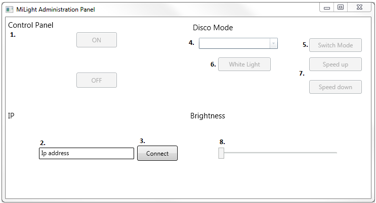
figure 3. administration panel sample application.
1. control panel with on/off switches.
2. ip address textbox.
3. connect button -> after click, application checks if ip address is typed correctly. if it is correct then rest of the buttons will be enabled, if not, an "incorrect ip number!" message will be displayed.
4. color picker -> infragistics color picker allows the user to pick one of the colors from the available palette.
5. switch mode button -> on first click, the application will turn on disco mode; every next click will switch to the next programmed illumination.
6. change color to white light.
7. speed up or slow down actual disco mode program.
8. brightness slider.
continuous integration (ci) signaling tool
with all that knowledge about the inner workings of this kind of lighting system, it is possible to create a continuous integration (ci) [2] physical tool that will use an rgbw wi-fi light bulb as an indicator of status of the build. it should simply:
- turn the light bulb green if all the builds are passing and everything is all right
- turn the light bulb yellow/orange if one or more builds are on the way
- turn the light bulb red if one or more of the builds failed
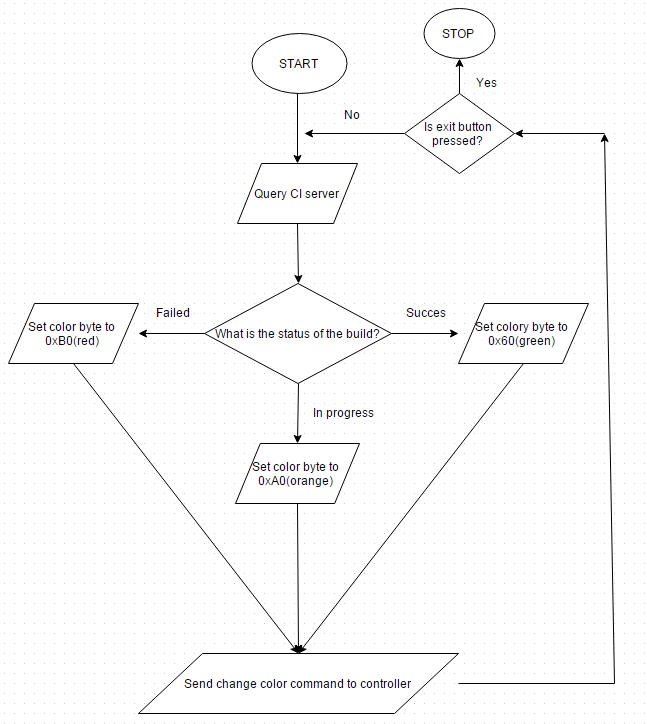
this application could work as seen on the simple schema in figure 4.
figure 4. sample application flow.
there are several ways to implement this kind of application. because it is an application that only shows the state of the ci server, it can be developed as a system tray application with a changing icon color. it could be easier to use than a normal windows forms/wpf style application as a windows service that queries the state of the build server. but, it seems the best way to implement it would be to write a plugin of an existing ci server that will turn the light bulb on and off with the correct color.
to not interrupt the workflow of the users, the controller needs to be connected directly to the existing network. nonstop network switching could be very annoying, so here are a few simple steps to connect the wi-fi controller to the existing network and assign a fixed ip address to it:
1) connect to the milight wi-fi network.
2) go to the administration panel via a web browser.
3) in work mode, change the work type to sta.
4) in the sta setting, change ssid to the name of your existing wi-fi network.
5) select the encryption type that your network is using right now.
6) enter your wi-fi password in the password box.
7) set "obtain an ip address automatically" to disable.
8) type the fixed ip address, subnet mask, gateway address, and dns server address (it may vary on your network configuration) to the proper boxes.
9) click "save" and restart the controller using the restart button located in the left menu bar
wait a while for the controller to join your existing wi-fi network and check it by typing the assigned ip address into your browser. if something went wrong and the controller is unable to connect your existing network, please reset the controller manually by sticking the end of a paperclip or needle into the reset hole located on the left of the micro usb port.
implementation of the code that queries the server can be different for every continuous integration (ci) solution.
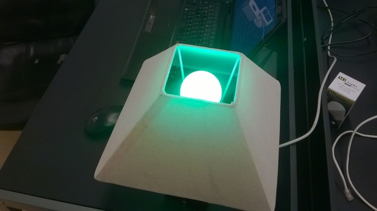
figure 5. ci build successful.
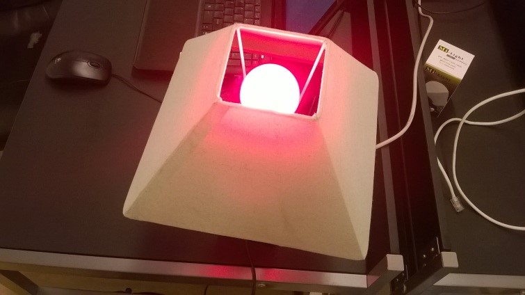
figure 6. ci build failed.
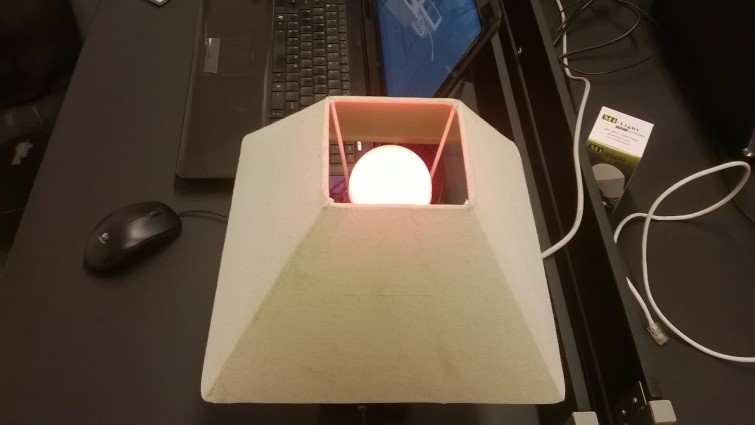
figure 7. ci build in progress.
conclusion
the main goal of this article was to show you how to steer the milight rgbw light bulb using .net. it’s a simple application that can be a foundation for a bigger system using rgbw light, like continuous integration server state signalization and more. we showed the most useful command patterns and how this kind of lighting system works... hope you enjoyed it. happy hacking!
documentation:
http://www.limitlessled.com/dev/
technical information:
http://www.philippinestuffs.com/milight-wifi-controlled-light-bulbs/
[1] http://www.infragistics.com/products/wpf/editors/color-picker
[2] https://en.wikipedia.org/wiki/continuous_integration
bring high volumes of complex information to life with infragistics wpf powerful data visualization capabilities! download a free trial now !
Published at DZone with permission of Josh Anderson, DZone MVB. See the original article here.
Opinions expressed by DZone contributors are their own.

Comments